
User Manual Owner's manual
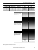
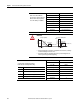
Table Of Contents
- ArmorStart Distributed Motor Controller with EtherNet/IP User Manual
- European Communities (EC) Directive Compliance
- Table of Contents
- Chapter 1
- Product Overview
- Introduction
- Description
- Catalog Number Explanation
- Operation
- Mode of Operation
- Description of Features
- Embedded Switch Technology
- Switched vs. Unswitched Control Power Input/Output (I/O) Connections
- EtherNet/IP™ Ports
- Embedded Web Server
- EtherNet/IP LED Status Indication
- Control Module LED Status and Reset
- Electronic Data Sheet (EDS)
- Fault Diagnostics
- Standard Features
- Factory-Installed Options
- Optional HOA Keypad Configuration (Bulletin 280E/281E only)
- Optional HOA Selector Keypad with Jog Function (Bulletin 284E only)
- Source Brake Contactor and Connector (Bulletin 284E only)
- EMI Filter (Bulletin 284E only)
- Dynamic Brake Connector (Bulletin 284E only)
- IP67 Dynamic Brake Resistor (Bulletin 284E only)
- Output Contactor (Bulletin 284E only)
- Shielded Motor Cable (Bulletin 284E only)
- ArmorStart® EtherNet/ IP Features
- Notes:
- Product Overview
- Chapter 2
- Installation and Wiring
- Receiving
- Unpacking
- Inspecting
- Storing
- General Precautions
- Precautions for Bulletin 280E/281E Applications
- Precautions for Bulletin 284E Applications
- Dimensions
- Mount Orientation
- Operation
- Wiring
- Terminal Designations
- Control Power Wiring
- ArmorStart with EtherNet/IP Internal Wiring
- AC Supply Considerations for Bulletin 284E Units
- Electromagnetic Compatibility (EMC)
- Grounding
- ArmorConnect Power Media
- ArmorConnect Connections
- ArmorConnect Cable Ratings
- Ethernet and I/O Connections
- Power Connections
- Optional Locking Clip
- Installation and Wiring
- Chapter 3
- Chapter 4
- Chapter 5
- Chapter 6
- Chapter 7
- Bulletin 280E/281E/284E Programmable Parameters
- Basic Setup Parameters
- Parameter Groups
- ArmorStart EtherNet/IP Parameters
- Bulletin 280E/281E
- Bulletin 284E
- Basic Status Group
- Produced Assembly Config Group
- Starter Protection Group
- User I/O Configuration Group
- Miscellaneous Configuration Group
- Drive I/O Configuration Group (Bulletin 284E only)
- Drive Display Group (Bulletin 284E only)
- Drive Setup Group (Bulletin 284E only)
- Drive Advanced Setup Group (Bulletin 284E only)
- Clear a Type 1 Fault and Restart the Drive
- Clear an Overvoltage, Undervoltage, or Heatsink OvrTmp Fault without Restarting the Drive
- How StepLogic Works
- StepLogic Settings
- Linear List of Parameters for Bulletin 280E/281E and Bulletin 284E
- Bulletin 280E/281E/284E Programmable Parameters
- Chapter 8
- Chapter 9
- Chapter 10
- Chapter 11
- Chapter 12
- Appendix A
- Applying More Than One ArmorStart Motor Controller in a Single Branch Circuit on Industrial Machinery
- Introduction
- ArmorStart LT Product Family
- Multiple-Motor Branch Circuits and Motor Controllers Listed for Group Installation – General
- Maximum Fuse Ampere Rating According to 7.2.10.4(1) and 7.2.10.4(2)
- Explanatory Example
- Input and Output Conductors of Bulletin 290E and 291E Controllers (a)
- Input and Output Conductors of Bulletin 294E Controllers (b)
- Combined Load Conductors (c)
- Applying More Than One ArmorStart Motor Controller in a Single Branch Circuit on Industrial Machinery
- Appendix B
- CIP Information
- High Level Product Description
- CIP Explicit Connection Behavior
- CIP Object Requirements
- Identity Object
- Assembly Object
- Connection Manager Object
- Discrete Input Point Object
- Discrete Output Point Object
- Parameter Object
- Parameter Group Object
- Discrete Input Group Object
- Discrete Output Group Object
- Control Supervisor Object
- Overload Object
- Device Level Ring (DLR) Object
- Qos Object
- DPI Fault Object
- DPI Alarm Object
- Interface Object
- TCP/IP Interface Object
- Ethernet Link Object
- CIP Information
- Appendix C
- Using DeviceLogix
- DeviceLogix Programming
- DeviceLogix Programming Example
- Import and Export
- Bulletin 284 - VFD Preset Speed Example
- DeviceLogix Ladder Editor Example
- ArmorStart 280 and 281 Status Bits
- Bulletin 280 and 281 ArmorStart Fault Bits
- Bulletin 280 and 281 ArmorStart Outputs
- Bulletin 280 and 281 ArmorStart Produced Network Bits
- Bulletin 284 ArmorStart Status Bits
- Bulletin 284 ArmorStart Fault Bits
- Bulletin 284 ArmorStart Outputs
- Bulletin 284 ArmorStart Produced Network Bits
- Using DeviceLogix
- Appendix D
- Appendix E
- Appendix F
- Back Cover

166 Rockwell Automation Publication 280E-UM001B-EN-P – July 2012
Chapter 7 Bulletin 280E/281E/284E Programmable Parameters
Relay Out Sel
Sets the condition that changes the
state of the output relay contacts.
Parameter Number 155
Related Parameters 133, 156, 192, 240…247,
250…257, 260, 261
Access Rule GET/SET
Data Type UINT
Group Drive Advanced Setup
Units —
Minimum Value 0
Maximum Value 22
Default Value 22
Table 21 - Options for the Output Relay Contacts
Options Name Description
0 Ready/Fault (Default)
Relay changes state when power is applied. This indicates the drive is ready for operation. Relay returns drive to shelf state when power is
removed or a fault occurs.
1 At Frequency Drive reached commanded frequency.
2 MotorRunning Motor is receiving power from drive.
3 Reverse Drive is commanded to run in reverse direction.
4 Motor Overld Motor overload condition exists.
5 Ramp Reg Ramp regulator is modifying the programmed accel/decal times to avoid overcurrent or overvoltage fault from occurring.
6 Above Freq Drive exceeds the frequency (Hz) value set in Parameter 156 (Relay Out Level) Use Parameter 156 to set threshold.
7 Above Cur Drive exceeds the current (% Amps) value set in Parameter 156 (Relay Out Level) Use Parameter 156 to set threshold.
8 Above DCVolt Drive exceeds the DC bus voltage value set in Parameter 156 (Relay Out Level). Use Parameter 156 to set threshold.
9 Retries Exst Value set in Parameter 192 (Auto Rstrt Tries) is exceeded.
10 Above Anlg V Option not valid for Bulletin 284E ArmorStart.
11 Logic In 1 An input is programmed as Logic In 1 and is active.
12 Logic In 2 An input is programmed as Logic In 2 and is active.
13 Logic In 1 & 2 Both Logic inputs are programmed and active.
14 Logic In 1 or 2 One or both Logic inputs are programmed and one or both is active.
15 StpLogic Out Drive enters StepLogic step with Digit 3 of Command Word (Parameters 240…247).
16 Timer Out Timer has reached value set in Parameter 156 (Relay Out Level). Use Parameter 156 to set threshold.
17 Counter Out Counter has reached value set in Parameter 156 (Relay Out Level). Use Parameter 156 to set threshold.
18 Above PF Ang Power factor angle has exceeded the value set in Parameter 156 (Relay Out Level). Use Parameter 156 to set threshold.
19 Anlg In Loss Option not valid for Bulletin 284E ArmorStart.
20 ParamControl Enables the output to be controlled over the network communications by writing to Parameter 156 (Relay Out Level) (0 = OFF, 1 = ON).
21 NonRec Fault Value set in Parameter 192 (Auto Rstrt Tries) is exceeded.
22 EM Brk Cntrl EM Brake is energized. Program Parameter 260 (EM Brk OFF Delay) and Parameter 261 (EM Brk On Delay) for desired action.
23 Above Fcmd The Current Command Frequency exceeds the value set in Parameter 156 (Relay Out Level).
24 Msg Control With Drive FRN4.01 or later, this option enables the output to be controlled over the network communication.