
User Manual Owner's manual

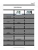
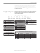
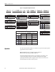
Table Of Contents
- ArmorStart Distributed Motor Controller with EtherNet/IP User Manual
- European Communities (EC) Directive Compliance
- Table of Contents
- Chapter 1
- Product Overview
- Introduction
- Description
- Catalog Number Explanation
- Operation
- Mode of Operation
- Description of Features
- Embedded Switch Technology
- Switched vs. Unswitched Control Power Input/Output (I/O) Connections
- EtherNet/IP™ Ports
- Embedded Web Server
- EtherNet/IP LED Status Indication
- Control Module LED Status and Reset
- Electronic Data Sheet (EDS)
- Fault Diagnostics
- Standard Features
- Factory-Installed Options
- Optional HOA Keypad Configuration (Bulletin 280E/281E only)
- Optional HOA Selector Keypad with Jog Function (Bulletin 284E only)
- Source Brake Contactor and Connector (Bulletin 284E only)
- EMI Filter (Bulletin 284E only)
- Dynamic Brake Connector (Bulletin 284E only)
- IP67 Dynamic Brake Resistor (Bulletin 284E only)
- Output Contactor (Bulletin 284E only)
- Shielded Motor Cable (Bulletin 284E only)
- ArmorStart® EtherNet/ IP Features
- Notes:
- Product Overview
- Chapter 2
- Installation and Wiring
- Receiving
- Unpacking
- Inspecting
- Storing
- General Precautions
- Precautions for Bulletin 280E/281E Applications
- Precautions for Bulletin 284E Applications
- Dimensions
- Mount Orientation
- Operation
- Wiring
- Terminal Designations
- Control Power Wiring
- ArmorStart with EtherNet/IP Internal Wiring
- AC Supply Considerations for Bulletin 284E Units
- Electromagnetic Compatibility (EMC)
- Grounding
- ArmorConnect Power Media
- ArmorConnect Connections
- ArmorConnect Cable Ratings
- Ethernet and I/O Connections
- Power Connections
- Optional Locking Clip
- Installation and Wiring
- Chapter 3
- Chapter 4
- Chapter 5
- Chapter 6
- Chapter 7
- Bulletin 280E/281E/284E Programmable Parameters
- Basic Setup Parameters
- Parameter Groups
- ArmorStart EtherNet/IP Parameters
- Bulletin 280E/281E
- Bulletin 284E
- Basic Status Group
- Produced Assembly Config Group
- Starter Protection Group
- User I/O Configuration Group
- Miscellaneous Configuration Group
- Drive I/O Configuration Group (Bulletin 284E only)
- Drive Display Group (Bulletin 284E only)
- Drive Setup Group (Bulletin 284E only)
- Drive Advanced Setup Group (Bulletin 284E only)
- Clear a Type 1 Fault and Restart the Drive
- Clear an Overvoltage, Undervoltage, or Heatsink OvrTmp Fault without Restarting the Drive
- How StepLogic Works
- StepLogic Settings
- Linear List of Parameters for Bulletin 280E/281E and Bulletin 284E
- Bulletin 280E/281E/284E Programmable Parameters
- Chapter 8
- Chapter 9
- Chapter 10
- Chapter 11
- Chapter 12
- Appendix A
- Applying More Than One ArmorStart Motor Controller in a Single Branch Circuit on Industrial Machinery
- Introduction
- ArmorStart LT Product Family
- Multiple-Motor Branch Circuits and Motor Controllers Listed for Group Installation – General
- Maximum Fuse Ampere Rating According to 7.2.10.4(1) and 7.2.10.4(2)
- Explanatory Example
- Input and Output Conductors of Bulletin 290E and 291E Controllers (a)
- Input and Output Conductors of Bulletin 294E Controllers (b)
- Combined Load Conductors (c)
- Applying More Than One ArmorStart Motor Controller in a Single Branch Circuit on Industrial Machinery
- Appendix B
- CIP Information
- High Level Product Description
- CIP Explicit Connection Behavior
- CIP Object Requirements
- Identity Object
- Assembly Object
- Connection Manager Object
- Discrete Input Point Object
- Discrete Output Point Object
- Parameter Object
- Parameter Group Object
- Discrete Input Group Object
- Discrete Output Group Object
- Control Supervisor Object
- Overload Object
- Device Level Ring (DLR) Object
- Qos Object
- DPI Fault Object
- DPI Alarm Object
- Interface Object
- TCP/IP Interface Object
- Ethernet Link Object
- CIP Information
- Appendix C
- Using DeviceLogix
- DeviceLogix Programming
- DeviceLogix Programming Example
- Import and Export
- Bulletin 284 - VFD Preset Speed Example
- DeviceLogix Ladder Editor Example
- ArmorStart 280 and 281 Status Bits
- Bulletin 280 and 281 ArmorStart Fault Bits
- Bulletin 280 and 281 ArmorStart Outputs
- Bulletin 280 and 281 ArmorStart Produced Network Bits
- Bulletin 284 ArmorStart Status Bits
- Bulletin 284 ArmorStart Fault Bits
- Bulletin 284 ArmorStart Outputs
- Bulletin 284 ArmorStart Produced Network Bits
- Using DeviceLogix
- Appendix D
- Appendix E
- Appendix F
- Back Cover
18 Rockwell Automation Publication 280E-UM001B-EN-P - July 2012
Chapter 1 Product Overview
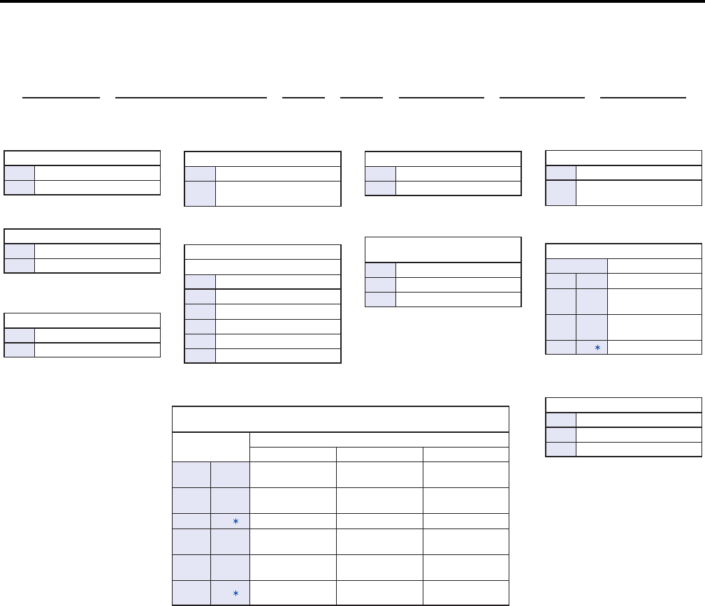
Figure 2 - Catalog Number Explanation for 284E
Operation
The ArmorStart Distributed Motor Controllers can operate three-phase squirrel-
cage induction motors as follows:
Bulletin 280E/281E: up to 10 Hp (7.4 kW) at 480V AC
Bulletin 284E: up to 5 Hp (3.0 kW) at 480V AC
ArmorStart EtherNet/IP Controllers accept 24V DC control voltage. The
control voltage will provide power to inputs (unswitched) and outputs
(switched). Unswitched control voltage is used to ensure no loss of sensor or
other field input status under normal operation.
g
Short Circuit Protection (Motor
Circuit Protector)
Code Description
10 10 A Rated Device
25 25 A Rated Device
a
Bulletin Number
Code Description
284 VFD Starter
d
Torque Performance Mode
Code Description
V
Sensorless Vector Control
and Volts per Hertz
i
Option 1
Code Description
3
Hand/Off/Auto Selector
Keypad with Jog Function
h
Control and 3-Phase Power Connections / Motor Cable Connection
(CR: Conduit/Round Media) or (RR: Round/Round Media)
Code
Description
Control Power 3-Phase Power Motor Cable
CR blank Conduit Entrance Conduit Entrance
3 m, unshielded
cordset male 90°
CR N Conduit Entrance Conduit Entrance
3 m, shielded
cordset male 90°
CR
W
Conduit Entrance Conduit Entrance No cable
RR blank
Round Media
(Male Receptacle)
Round Media
(Male Receptacle)
3 m, unshielded
cordset male 90°
RR N
Round Media
(Male Receptacle)
Round Media
(Male Receptacle)
3 m, shielded
cordset male 90°
RR
W
Round Media
(Male Receptacle)
Round Media
(Male Receptacle)
No cable
284 E – F V D2P3 D – 10 – CR – Option 1 – Option 2 – Option 3
ab cd e f g h i j k
b
Communications
Code Description
E EtherNet/IP
c
Enclosure Type
Code Description
F Type 4 (IP67)
e
Output Current
380…480V
Code Description
D1P4 1.4 A, 0.4 kW, 0.5 Hp
D2P3 2.3 A, 0.75 kW, 1.0 Hp
D4P0 4.0 A, 1.5 kW, 2.0 Hp
D6P0 6.0 A, 2.2 kW, 3.0 Hp
D7P6 7.6 A, 3.3 kW, 5.0 Hp
j
Option 2
Code Description
DB blank DB Brake Connector
DB1 blank
Connectivity to IP67
DB Resistor
SB blank
Source Brake
Contactor
SB
W
No cable
k
Option 3
Code Description
EMI EMI Filter
OC Output Contactor
f
Control Voltage
Code Description
Z 24V DC