
User Manual Owner's manual
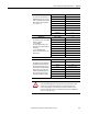
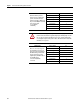
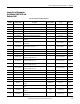
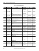
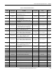
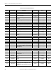
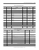
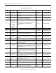
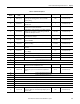

Table Of Contents
- ArmorStart Distributed Motor Controller with EtherNet/IP User Manual
- European Communities (EC) Directive Compliance
- Table of Contents
- Chapter 1
- Product Overview
- Introduction
- Description
- Catalog Number Explanation
- Operation
- Mode of Operation
- Description of Features
- Embedded Switch Technology
- Switched vs. Unswitched Control Power Input/Output (I/O) Connections
- EtherNet/IP™ Ports
- Embedded Web Server
- EtherNet/IP LED Status Indication
- Control Module LED Status and Reset
- Electronic Data Sheet (EDS)
- Fault Diagnostics
- Standard Features
- Factory-Installed Options
- Optional HOA Keypad Configuration (Bulletin 280E/281E only)
- Optional HOA Selector Keypad with Jog Function (Bulletin 284E only)
- Source Brake Contactor and Connector (Bulletin 284E only)
- EMI Filter (Bulletin 284E only)
- Dynamic Brake Connector (Bulletin 284E only)
- IP67 Dynamic Brake Resistor (Bulletin 284E only)
- Output Contactor (Bulletin 284E only)
- Shielded Motor Cable (Bulletin 284E only)
- ArmorStart® EtherNet/ IP Features
- Notes:
- Product Overview
- Chapter 2
- Installation and Wiring
- Receiving
- Unpacking
- Inspecting
- Storing
- General Precautions
- Precautions for Bulletin 280E/281E Applications
- Precautions for Bulletin 284E Applications
- Dimensions
- Mount Orientation
- Operation
- Wiring
- Terminal Designations
- Control Power Wiring
- ArmorStart with EtherNet/IP Internal Wiring
- AC Supply Considerations for Bulletin 284E Units
- Electromagnetic Compatibility (EMC)
- Grounding
- ArmorConnect Power Media
- ArmorConnect Connections
- ArmorConnect Cable Ratings
- Ethernet and I/O Connections
- Power Connections
- Optional Locking Clip
- Installation and Wiring
- Chapter 3
- Chapter 4
- Chapter 5
- Chapter 6
- Chapter 7
- Bulletin 280E/281E/284E Programmable Parameters
- Basic Setup Parameters
- Parameter Groups
- ArmorStart EtherNet/IP Parameters
- Bulletin 280E/281E
- Bulletin 284E
- Basic Status Group
- Produced Assembly Config Group
- Starter Protection Group
- User I/O Configuration Group
- Miscellaneous Configuration Group
- Drive I/O Configuration Group (Bulletin 284E only)
- Drive Display Group (Bulletin 284E only)
- Drive Setup Group (Bulletin 284E only)
- Drive Advanced Setup Group (Bulletin 284E only)
- Clear a Type 1 Fault and Restart the Drive
- Clear an Overvoltage, Undervoltage, or Heatsink OvrTmp Fault without Restarting the Drive
- How StepLogic Works
- StepLogic Settings
- Linear List of Parameters for Bulletin 280E/281E and Bulletin 284E
- Bulletin 280E/281E/284E Programmable Parameters
- Chapter 8
- Chapter 9
- Chapter 10
- Chapter 11
- Chapter 12
- Appendix A
- Applying More Than One ArmorStart Motor Controller in a Single Branch Circuit on Industrial Machinery
- Introduction
- ArmorStart LT Product Family
- Multiple-Motor Branch Circuits and Motor Controllers Listed for Group Installation – General
- Maximum Fuse Ampere Rating According to 7.2.10.4(1) and 7.2.10.4(2)
- Explanatory Example
- Input and Output Conductors of Bulletin 290E and 291E Controllers (a)
- Input and Output Conductors of Bulletin 294E Controllers (b)
- Combined Load Conductors (c)
- Applying More Than One ArmorStart Motor Controller in a Single Branch Circuit on Industrial Machinery
- Appendix B
- CIP Information
- High Level Product Description
- CIP Explicit Connection Behavior
- CIP Object Requirements
- Identity Object
- Assembly Object
- Connection Manager Object
- Discrete Input Point Object
- Discrete Output Point Object
- Parameter Object
- Parameter Group Object
- Discrete Input Group Object
- Discrete Output Group Object
- Control Supervisor Object
- Overload Object
- Device Level Ring (DLR) Object
- Qos Object
- DPI Fault Object
- DPI Alarm Object
- Interface Object
- TCP/IP Interface Object
- Ethernet Link Object
- CIP Information
- Appendix C
- Using DeviceLogix
- DeviceLogix Programming
- DeviceLogix Programming Example
- Import and Export
- Bulletin 284 - VFD Preset Speed Example
- DeviceLogix Ladder Editor Example
- ArmorStart 280 and 281 Status Bits
- Bulletin 280 and 281 ArmorStart Fault Bits
- Bulletin 280 and 281 ArmorStart Outputs
- Bulletin 280 and 281 ArmorStart Produced Network Bits
- Bulletin 284 ArmorStart Status Bits
- Bulletin 284 ArmorStart Fault Bits
- Bulletin 284 ArmorStart Outputs
- Bulletin 284 ArmorStart Produced Network Bits
- Using DeviceLogix
- Appendix D
- Appendix E
- Appendix F
- Back Cover

196 Rockwell Automation Publication 280E-UM001B-EN-P - July 2012
Chapter 7 Bulletin 280E/281E/284E Programmable Parameters
105 Therm Utilized
This parameter displays the % Thermal Capacity used.
0Starter DisplayDOL
106 FLA Setting
The motor’s full load current rating
See Table 19. Starter Setup DOL
107 Overload Class
Selects the overload class.
1 =
Overload Class 10
Starter Setup DOL
108 OL Reset Level
Selects the % Thermal Capacity which an overload can
be cleared.
75 Starter Setup DOL
101 Output Freq
Output frequency present at T1, T2 & T3 (U, V & W)
Read Only Drive Display 284E
102 Commanded Freq
Value of the active frequency command
Read Only Drive Display 284E
103 Output Current
Output current present at T1, T2 & T3 (U, V & W)
Read Only Drive Display 284E
104 Output Voltage
Output voltage present at T1, T2 & T3 (U, V & W)
Read Only Drive Display 284E
105 DC Bus Voltage
Present DC bus voltage level
Read Only Drive Display 284E
106 Drive Status
Present operating condition of the drive.
Read Only Drive Display 284E
107…109 Fault x Code
A code that represents a drive fault.
Read Only Drive Display 284E
110 Process Display
The output frequency scaled by Parameter 199 (Process
Factor).
Read Only Drive Display 284E
112 Control Source
Displays the source of the Start Command and Speed
Reference.
5 =
RS485 (DSI) Port
Drive Display 284E
113 Option not valid for Bulletin 284E ArmorStart.
114 Dig In Status
Status of the control terminal block digital inputs.
0Drive Display284E
115 Comm Status
Status of the communications ports
0Drive Display284E
116 Control SW Ver
Main Control Board software version for AC Drive.
Read Only Drive Display 284E
117 Drive Type
Used by Rockwell Automation field service personnel.
Read Only Drive Display 284E
118 Elapsed Run Time
Accumulated time drive is outputting power.
Read Only Drive Display 284E
119 Testpoint Data
The present value of the function selected in Parameter
202 (Testpoint Sel).
Read Only Drive Display 284E
120 Option not valid for Bulletin 284E ArmorStart.
121 Option not valid for Bulletin 284E ArmorStart.
122 Output Power
Output power present at T1, T2 & T3 (U, V & W).
Read Only Drive Display 284E
123 Output Power Fctr
The angle in electrical degrees between motor voltage
and motor current.
Read Only Drive Display 284E
124 Drive Temp
Present operating temperature of the drive power
section.
Read Only Drive Display 284E
125 Counter Status
The current value of the counter when counter is
enabled.
Read Only Drive Display 284E
126 Timer Status
The current value of the timer when timer is enabled.
Read Only Drive Display 284E
128 StpLogic Status
When Parameter 138 (Speed Reference) is set to "6"
(StpLogic), this parameter will display the current
StepLogic profile as defined by Parameters 240-247
(StpLogic x).
Read Only Drive Display 284E
Table 28 - ArmorStart Common Parameters
Parameter
Number Parameter Name Description Factory Default Group Controller