
User Manual Owner's manual
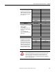
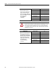
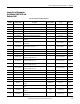
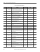
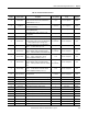
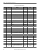
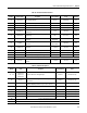
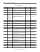
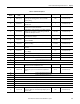

Table Of Contents
- ArmorStart Distributed Motor Controller with EtherNet/IP User Manual
- European Communities (EC) Directive Compliance
- Table of Contents
- Chapter 1
- Product Overview
- Introduction
- Description
- Catalog Number Explanation
- Operation
- Mode of Operation
- Description of Features
- Embedded Switch Technology
- Switched vs. Unswitched Control Power Input/Output (I/O) Connections
- EtherNet/IP™ Ports
- Embedded Web Server
- EtherNet/IP LED Status Indication
- Control Module LED Status and Reset
- Electronic Data Sheet (EDS)
- Fault Diagnostics
- Standard Features
- Factory-Installed Options
- Optional HOA Keypad Configuration (Bulletin 280E/281E only)
- Optional HOA Selector Keypad with Jog Function (Bulletin 284E only)
- Source Brake Contactor and Connector (Bulletin 284E only)
- EMI Filter (Bulletin 284E only)
- Dynamic Brake Connector (Bulletin 284E only)
- IP67 Dynamic Brake Resistor (Bulletin 284E only)
- Output Contactor (Bulletin 284E only)
- Shielded Motor Cable (Bulletin 284E only)
- ArmorStart® EtherNet/ IP Features
- Notes:
- Product Overview
- Chapter 2
- Installation and Wiring
- Receiving
- Unpacking
- Inspecting
- Storing
- General Precautions
- Precautions for Bulletin 280E/281E Applications
- Precautions for Bulletin 284E Applications
- Dimensions
- Mount Orientation
- Operation
- Wiring
- Terminal Designations
- Control Power Wiring
- ArmorStart with EtherNet/IP Internal Wiring
- AC Supply Considerations for Bulletin 284E Units
- Electromagnetic Compatibility (EMC)
- Grounding
- ArmorConnect Power Media
- ArmorConnect Connections
- ArmorConnect Cable Ratings
- Ethernet and I/O Connections
- Power Connections
- Optional Locking Clip
- Installation and Wiring
- Chapter 3
- Chapter 4
- Chapter 5
- Chapter 6
- Chapter 7
- Bulletin 280E/281E/284E Programmable Parameters
- Basic Setup Parameters
- Parameter Groups
- ArmorStart EtherNet/IP Parameters
- Bulletin 280E/281E
- Bulletin 284E
- Basic Status Group
- Produced Assembly Config Group
- Starter Protection Group
- User I/O Configuration Group
- Miscellaneous Configuration Group
- Drive I/O Configuration Group (Bulletin 284E only)
- Drive Display Group (Bulletin 284E only)
- Drive Setup Group (Bulletin 284E only)
- Drive Advanced Setup Group (Bulletin 284E only)
- Clear a Type 1 Fault and Restart the Drive
- Clear an Overvoltage, Undervoltage, or Heatsink OvrTmp Fault without Restarting the Drive
- How StepLogic Works
- StepLogic Settings
- Linear List of Parameters for Bulletin 280E/281E and Bulletin 284E
- Bulletin 280E/281E/284E Programmable Parameters
- Chapter 8
- Chapter 9
- Chapter 10
- Chapter 11
- Chapter 12
- Appendix A
- Applying More Than One ArmorStart Motor Controller in a Single Branch Circuit on Industrial Machinery
- Introduction
- ArmorStart LT Product Family
- Multiple-Motor Branch Circuits and Motor Controllers Listed for Group Installation – General
- Maximum Fuse Ampere Rating According to 7.2.10.4(1) and 7.2.10.4(2)
- Explanatory Example
- Input and Output Conductors of Bulletin 290E and 291E Controllers (a)
- Input and Output Conductors of Bulletin 294E Controllers (b)
- Combined Load Conductors (c)
- Applying More Than One ArmorStart Motor Controller in a Single Branch Circuit on Industrial Machinery
- Appendix B
- CIP Information
- High Level Product Description
- CIP Explicit Connection Behavior
- CIP Object Requirements
- Identity Object
- Assembly Object
- Connection Manager Object
- Discrete Input Point Object
- Discrete Output Point Object
- Parameter Object
- Parameter Group Object
- Discrete Input Group Object
- Discrete Output Group Object
- Control Supervisor Object
- Overload Object
- Device Level Ring (DLR) Object
- Qos Object
- DPI Fault Object
- DPI Alarm Object
- Interface Object
- TCP/IP Interface Object
- Ethernet Link Object
- CIP Information
- Appendix C
- Using DeviceLogix
- DeviceLogix Programming
- DeviceLogix Programming Example
- Import and Export
- Bulletin 284 - VFD Preset Speed Example
- DeviceLogix Ladder Editor Example
- ArmorStart 280 and 281 Status Bits
- Bulletin 280 and 281 ArmorStart Fault Bits
- Bulletin 280 and 281 ArmorStart Outputs
- Bulletin 280 and 281 ArmorStart Produced Network Bits
- Bulletin 284 ArmorStart Status Bits
- Bulletin 284 ArmorStart Fault Bits
- Bulletin 284 ArmorStart Outputs
- Bulletin 284 ArmorStart Produced Network Bits
- Using DeviceLogix
- Appendix D
- Appendix E
- Appendix F
- Back Cover

200 Rockwell Automation Publication 280E-UM001B-EN-P - July 2012
Chapter 7 Bulletin 280E/281E/284E Programmable Parameters
215 Process Time Lo
Scales the time value when the drive is running at Parameter 134
(Minimum Freq). When set to a value other than zero, Parameter
110 (Process Display) indicates the duration of the process.
0.00 Drive Advanced Setup
216 Process Time Hi
Scales the time value when the drive is running at Parameter 135
(Maximum Freq). When set to a value other than zero, Parameter
110 (Process Display) indicates the duration of the process.
0.00 Drive Advanced Setup
217 Bus Reg Mode
Enables the bus regulator.
1 = Enabled Drive Advanced Setup
218 Current Limit 2
Maximum output current allowed before current limiting occurs.
Drive Rated
Amps x 1.5
Drive Advanced Setup
219 Skip Frequency
Sets the frequency at which the drive will not operate.
0.0 Hz Drive Advanced Setup
220 Skip Freq Band
Determines the brand width around Parameter 219 (Skip
Frequency). Parameter 220 (Skip Freq Band) is split applying 1/2
above and 1/2 below the actual skip frequency.
0.0 Hz Drive Advanced Setup
221 Stall Fault Time
Sets for the fault time that the drive will remain in stall mode
before a fault is issued.
0 = 60 Seconds Drive Advanced Setup
222 Option not valid for Bulletin 284E ArmorStart.
223 Option not valid for Bulletin 284E ArmorStart.
224 Var PWM Disable
Enables/disables a feature that varies the carrier frequency for
the PWM output waveform defined by Parameter 191 (PWM
Frequency).
0 = Enabled Drive Advanced Setup
225 Torque Perf Mode
Enables/disables sensorless vector control operation.
1 = Sensrls Vect Drive Advanced Setup
226 Motor NP FLA
Set to the motor nameplate full load amps.
Drive Rated Amps Drive Advanced Setup
227 Autotune
Provides an automatic method for setting Parameter 228
(IR Voltage Drop) and Parameter 229 (Flux Current Ref), which
affect sensorless vector performance.
0 = Ready/Idle Drive Advanced Setup
228 IR Voltage Drop
Value of volts dropped across the resistance of the motor stator.
Based on Drive
Rating
Drive Advanced Setup
229 Flux Current Ref
Value of amps for full motor flux.
Based on Drive
Rating
Drive Advanced Setup
230 PID Trim Hi
Sets the maximum positive value that is added to a PID reference
when PID trim is used.
60.0 Drive Advanced Setup
231 PID Trim Lo
Sets the minimum positive value that is added to a PID reference
when PID trim is used.
0.1 Drive Advanced Setup
232 PID Ref Sel
Enables/disables PID mode and selects the source of the PID
reference.
0 = PID Disabled Drive Advanced Setup
233 PID Feedback Sel
Valid PID Feedback Sel command for the Bulletin 284E
ArmorStart.
0 = 0-10V Input Drive Advanced Setup
234 PID Prop Gain
Sets the value for the PID proportional component when the PID
mode is enabled by Parameter 232 (PID Ref Sel).
0.01 Drive Advanced Setup
235 PID Integ Time
Sets the value for the PID integral component when the PID mode
is enabled by Parameter 232 (PID Ref Sel).
0.1 Secs Drive Advanced Setup
236 PID Diff Rate
Sets the value for the PID differential component when the PID
mode is enabled by Parameter 232 (PID Rel Sel).
0.01 (1/Secs) Drive Advanced Setup
Table 29 - Parameter Descriptions
Parameter
Number
Parameter
Name
Description Factory Default Group