
User Manual Owner's manual
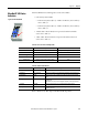
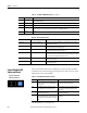
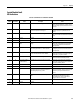
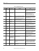
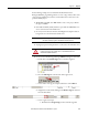
Table Of Contents
- ArmorStart Distributed Motor Controller with EtherNet/IP User Manual
- European Communities (EC) Directive Compliance
- Table of Contents
- Chapter 1
- Product Overview
- Introduction
- Description
- Catalog Number Explanation
- Operation
- Mode of Operation
- Description of Features
- Embedded Switch Technology
- Switched vs. Unswitched Control Power Input/Output (I/O) Connections
- EtherNet/IP™ Ports
- Embedded Web Server
- EtherNet/IP LED Status Indication
- Control Module LED Status and Reset
- Electronic Data Sheet (EDS)
- Fault Diagnostics
- Standard Features
- Factory-Installed Options
- Optional HOA Keypad Configuration (Bulletin 280E/281E only)
- Optional HOA Selector Keypad with Jog Function (Bulletin 284E only)
- Source Brake Contactor and Connector (Bulletin 284E only)
- EMI Filter (Bulletin 284E only)
- Dynamic Brake Connector (Bulletin 284E only)
- IP67 Dynamic Brake Resistor (Bulletin 284E only)
- Output Contactor (Bulletin 284E only)
- Shielded Motor Cable (Bulletin 284E only)
- ArmorStart® EtherNet/ IP Features
- Notes:
- Product Overview
- Chapter 2
- Installation and Wiring
- Receiving
- Unpacking
- Inspecting
- Storing
- General Precautions
- Precautions for Bulletin 280E/281E Applications
- Precautions for Bulletin 284E Applications
- Dimensions
- Mount Orientation
- Operation
- Wiring
- Terminal Designations
- Control Power Wiring
- ArmorStart with EtherNet/IP Internal Wiring
- AC Supply Considerations for Bulletin 284E Units
- Electromagnetic Compatibility (EMC)
- Grounding
- ArmorConnect Power Media
- ArmorConnect Connections
- ArmorConnect Cable Ratings
- Ethernet and I/O Connections
- Power Connections
- Optional Locking Clip
- Installation and Wiring
- Chapter 3
- Chapter 4
- Chapter 5
- Chapter 6
- Chapter 7
- Bulletin 280E/281E/284E Programmable Parameters
- Basic Setup Parameters
- Parameter Groups
- ArmorStart EtherNet/IP Parameters
- Bulletin 280E/281E
- Bulletin 284E
- Basic Status Group
- Produced Assembly Config Group
- Starter Protection Group
- User I/O Configuration Group
- Miscellaneous Configuration Group
- Drive I/O Configuration Group (Bulletin 284E only)
- Drive Display Group (Bulletin 284E only)
- Drive Setup Group (Bulletin 284E only)
- Drive Advanced Setup Group (Bulletin 284E only)
- Clear a Type 1 Fault and Restart the Drive
- Clear an Overvoltage, Undervoltage, or Heatsink OvrTmp Fault without Restarting the Drive
- How StepLogic Works
- StepLogic Settings
- Linear List of Parameters for Bulletin 280E/281E and Bulletin 284E
- Bulletin 280E/281E/284E Programmable Parameters
- Chapter 8
- Chapter 9
- Chapter 10
- Chapter 11
- Chapter 12
- Appendix A
- Applying More Than One ArmorStart Motor Controller in a Single Branch Circuit on Industrial Machinery
- Introduction
- ArmorStart LT Product Family
- Multiple-Motor Branch Circuits and Motor Controllers Listed for Group Installation – General
- Maximum Fuse Ampere Rating According to 7.2.10.4(1) and 7.2.10.4(2)
- Explanatory Example
- Input and Output Conductors of Bulletin 290E and 291E Controllers (a)
- Input and Output Conductors of Bulletin 294E Controllers (b)
- Combined Load Conductors (c)
- Applying More Than One ArmorStart Motor Controller in a Single Branch Circuit on Industrial Machinery
- Appendix B
- CIP Information
- High Level Product Description
- CIP Explicit Connection Behavior
- CIP Object Requirements
- Identity Object
- Assembly Object
- Connection Manager Object
- Discrete Input Point Object
- Discrete Output Point Object
- Parameter Object
- Parameter Group Object
- Discrete Input Group Object
- Discrete Output Group Object
- Control Supervisor Object
- Overload Object
- Device Level Ring (DLR) Object
- Qos Object
- DPI Fault Object
- DPI Alarm Object
- Interface Object
- TCP/IP Interface Object
- Ethernet Link Object
- CIP Information
- Appendix C
- Using DeviceLogix
- DeviceLogix Programming
- DeviceLogix Programming Example
- Import and Export
- Bulletin 284 - VFD Preset Speed Example
- DeviceLogix Ladder Editor Example
- ArmorStart 280 and 281 Status Bits
- Bulletin 280 and 281 ArmorStart Fault Bits
- Bulletin 280 and 281 ArmorStart Outputs
- Bulletin 280 and 281 ArmorStart Produced Network Bits
- Bulletin 284 ArmorStart Status Bits
- Bulletin 284 ArmorStart Fault Bits
- Bulletin 284 ArmorStart Outputs
- Bulletin 284 ArmorStart Produced Network Bits
- Using DeviceLogix
- Appendix D
- Appendix E
- Appendix F
- Back Cover
212 Rockwell Automation Publication 280E-UM001B-EN-P - July 2012
Chapter 9 Diagnostics
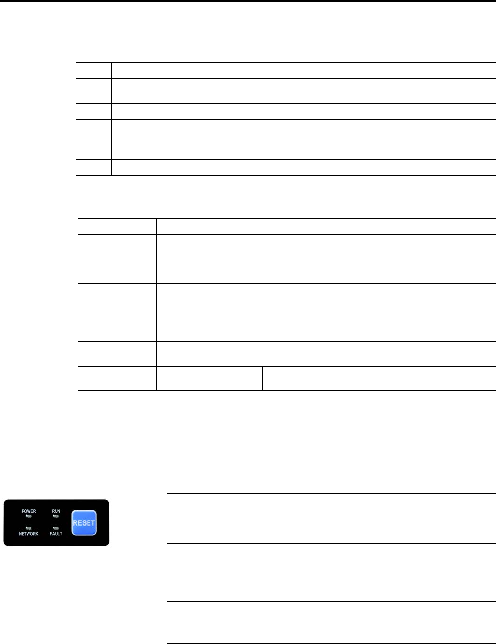
Control Module LED
Status and Reset
The Control Module LED status and diagnostics consists of four status LEDs
and a Reset button. The following is a brief explanation of the operation of each
LED found on the Control Module.
The “Reset Button” is a local trip reset.
Table 33 - “Steady Red” MOD LED Status (Refer to Table 32.)
Fault Type Description
0 EEPROM Fault Non-volatile memory value out of range for a local parameter, or a write failure detected. This fault is also reflected by
a solid red MOD status LED.
1 Internal Comm2 The Internal communication connection has timed out. This fault is also reflected by a flashing red MOD status LED.
2 Hardware Fault Internal diagnostics checks failed. This fault is also reflected by a solid red MOD status LED.
3 Control Module An illegal or unsupported Control Module product code or revision has been detected. Also reported if no Control
Module is detected on power up. This fault is also reflected by a solid red MOD status LED.
4…15 Reserved Reserved
Table 34 - Network Status Indicator
Indicator State Summary Requirement
Steady OFF Not powered, no IP address If the device does not have an IP address (or is powered OFF), the network status
indicator shall be steady OFF.
Flashing Green No connections If the device has no established connections, but has obtained an IP address, the
network status indicator shall be flashing green.
Steady Green Connected If the device has at least one established connection (even to the Message Router),
the network status indicator shall be steady green.
Flashing Red Connection timeout If one or more of the connections in which this device is the target has timed out,
the network status indicator shall be flashing red. This shall be left if only all timed
out connections are reestablished or if the device is reset.
Steady Red Duplicate IP If the device has detected that the IP addtress is already in use, the network status
indicator shal be steady red.
Flashing Red/Green Self-test While the device is performing its power up testing, the network status indicator
shall be flashing green/red.
Figure 81 - LED Status
Indication and Reset
Table 35 - Control Module LED Status Indication
LED Definition Recommended Action
Power This LED will be illuminated solid green when
switched control power is present and with the
proper polarity.
Ensure 24V DC is present on A1 and A2. Check if the
local disconnect is in the OFF position.
Run This LED will be illuminated solid green when a
start command and control power is present.
Ensure 24V DC is present on A1 and A3. Check if the
user is properly commanding to RUN via Instance
162 or 166.
Network This bicolor LED is used to indicate the status of the
internal network connection.
See Table 34, Network Status Indicator table above
for additional information.
Fault This LED is used to indicate the fault status of the
ArmorStart. When the unit is faulted, the unit will
respond with a specific blink pattern to identify the
fault.
See Table 36 and Table 37 below for additional
information.