
User Manual Owner's manual
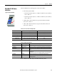
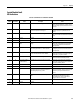
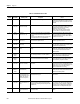
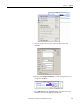
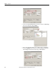
Table Of Contents
- ArmorStart Distributed Motor Controller with EtherNet/IP User Manual
- European Communities (EC) Directive Compliance
- Table of Contents
- Chapter 1
- Product Overview
- Introduction
- Description
- Catalog Number Explanation
- Operation
- Mode of Operation
- Description of Features
- Embedded Switch Technology
- Switched vs. Unswitched Control Power Input/Output (I/O) Connections
- EtherNet/IP™ Ports
- Embedded Web Server
- EtherNet/IP LED Status Indication
- Control Module LED Status and Reset
- Electronic Data Sheet (EDS)
- Fault Diagnostics
- Standard Features
- Factory-Installed Options
- Optional HOA Keypad Configuration (Bulletin 280E/281E only)
- Optional HOA Selector Keypad with Jog Function (Bulletin 284E only)
- Source Brake Contactor and Connector (Bulletin 284E only)
- EMI Filter (Bulletin 284E only)
- Dynamic Brake Connector (Bulletin 284E only)
- IP67 Dynamic Brake Resistor (Bulletin 284E only)
- Output Contactor (Bulletin 284E only)
- Shielded Motor Cable (Bulletin 284E only)
- ArmorStart® EtherNet/ IP Features
- Notes:
- Product Overview
- Chapter 2
- Installation and Wiring
- Receiving
- Unpacking
- Inspecting
- Storing
- General Precautions
- Precautions for Bulletin 280E/281E Applications
- Precautions for Bulletin 284E Applications
- Dimensions
- Mount Orientation
- Operation
- Wiring
- Terminal Designations
- Control Power Wiring
- ArmorStart with EtherNet/IP Internal Wiring
- AC Supply Considerations for Bulletin 284E Units
- Electromagnetic Compatibility (EMC)
- Grounding
- ArmorConnect Power Media
- ArmorConnect Connections
- ArmorConnect Cable Ratings
- Ethernet and I/O Connections
- Power Connections
- Optional Locking Clip
- Installation and Wiring
- Chapter 3
- Chapter 4
- Chapter 5
- Chapter 6
- Chapter 7
- Bulletin 280E/281E/284E Programmable Parameters
- Basic Setup Parameters
- Parameter Groups
- ArmorStart EtherNet/IP Parameters
- Bulletin 280E/281E
- Bulletin 284E
- Basic Status Group
- Produced Assembly Config Group
- Starter Protection Group
- User I/O Configuration Group
- Miscellaneous Configuration Group
- Drive I/O Configuration Group (Bulletin 284E only)
- Drive Display Group (Bulletin 284E only)
- Drive Setup Group (Bulletin 284E only)
- Drive Advanced Setup Group (Bulletin 284E only)
- Clear a Type 1 Fault and Restart the Drive
- Clear an Overvoltage, Undervoltage, or Heatsink OvrTmp Fault without Restarting the Drive
- How StepLogic Works
- StepLogic Settings
- Linear List of Parameters for Bulletin 280E/281E and Bulletin 284E
- Bulletin 280E/281E/284E Programmable Parameters
- Chapter 8
- Chapter 9
- Chapter 10
- Chapter 11
- Chapter 12
- Appendix A
- Applying More Than One ArmorStart Motor Controller in a Single Branch Circuit on Industrial Machinery
- Introduction
- ArmorStart LT Product Family
- Multiple-Motor Branch Circuits and Motor Controllers Listed for Group Installation – General
- Maximum Fuse Ampere Rating According to 7.2.10.4(1) and 7.2.10.4(2)
- Explanatory Example
- Input and Output Conductors of Bulletin 290E and 291E Controllers (a)
- Input and Output Conductors of Bulletin 294E Controllers (b)
- Combined Load Conductors (c)
- Applying More Than One ArmorStart Motor Controller in a Single Branch Circuit on Industrial Machinery
- Appendix B
- CIP Information
- High Level Product Description
- CIP Explicit Connection Behavior
- CIP Object Requirements
- Identity Object
- Assembly Object
- Connection Manager Object
- Discrete Input Point Object
- Discrete Output Point Object
- Parameter Object
- Parameter Group Object
- Discrete Input Group Object
- Discrete Output Group Object
- Control Supervisor Object
- Overload Object
- Device Level Ring (DLR) Object
- Qos Object
- DPI Fault Object
- DPI Alarm Object
- Interface Object
- TCP/IP Interface Object
- Ethernet Link Object
- CIP Information
- Appendix C
- Using DeviceLogix
- DeviceLogix Programming
- DeviceLogix Programming Example
- Import and Export
- Bulletin 284 - VFD Preset Speed Example
- DeviceLogix Ladder Editor Example
- ArmorStart 280 and 281 Status Bits
- Bulletin 280 and 281 ArmorStart Fault Bits
- Bulletin 280 and 281 ArmorStart Outputs
- Bulletin 280 and 281 ArmorStart Produced Network Bits
- Bulletin 284 ArmorStart Status Bits
- Bulletin 284 ArmorStart Fault Bits
- Bulletin 284 ArmorStart Outputs
- Bulletin 284 ArmorStart Produced Network Bits
- Using DeviceLogix
- Appendix D
- Appendix E
- Appendix F
- Back Cover

Rockwell Automation Publication 280E-UM001B-EN-P - July 2012 213
Diagnostics Chapter 9
Control Module Fault
LED Indications
Table 36 - Fault LED Indicators for Bulletin 280E/281E
Blink
Pattern
Auto-
Resettable
Bulletin 280E/281E Trip
Status Description Action
1 No Short Circuit The circuit breaker (140M) has tripped. Determine cause of trip. Try to reset the circuit breaker
using the disconnect handle. If the conditions continue,
check power wiring or replace based module. This cannot
be disabled.
2 Yes Overload The load has drawn excessive current and based on the
trip class selected, the device has tripped.
Verify that the load is operating correctly and the
ArmorStart is properly set-up. the fault cannot be
disabled.
3 Yes Phase Loss The ArmorStart has detected a missing phase. Verify that 3-phase voltage is present at the line side
connections. This fault can be disabled and is disabled by
default.
4 — Reserved Not Used —
5 — Reserved Not Used —
6 Yes Control Pwr Loss (Switched
Power)
The ArmorStart has detected a loss of the control power
voltage.
Check control voltage, wiring, and proper polarity (A1/A2
terminal). Also, check and replace the control voltage
fuse, if necessary. This fault can be disabled and is
disabled by default.
7 Yes Input Fault This error indicates a shorted sensor, shorted input
device, wiring input mistakes, or a blown output fuse.
Correct, isolated or remove wiring error prior to
restarting the system. This fault can be disabled and is
disabled by default.
8 Yes Over Temperature This fault is generated when the operating temperature
has been exceeded. This fault cannot be disabled.
Check for blocked or dirty heat sink fins. Verify that
ambient temperature has not exceeded 40 °C (104 °F). 1.
Clear the fault or cycle power to the drive.
9 Yes Phase Imbalance The ArmorStart has detected a voltage imbalance. Check the power system and correct if necessary. This
fault can be disabled and is disabled by default.
10 Yes Control Power (24V DC) Lost
(Unswitched Power)
The 24V DC power supply is below tolerance threshold. Check the state of the network power supply (A3/A1
terminal) and look for media problems. This fault can be
disabled and is disabled by default.
11 — Reserved Not Used —
12 — Reserved Not Used —
13 No EEprom This is a major fault, which renders the ArmorStart
inoperable. Possible causes of this fault are transients
induced during EEprom storage routines.
If the fault was initiated by a transient, power cycling
should clear the problem, otherwise replacement of the
ArmorStart may be required. This fault cannot be
disabled.
14 No Hdw Flt This fault indicates that a serious hardware problem
exists.
Check for a base/starter module mismatch. If no
mismatch exists, the ArmorStart may need to be
replaced. (Hdw Flt is the factory-enabled default
setting.) This fault cannot be disabled.
15 — Reserved Not Used —
16 — Reserved Not Used —