
User Manual Owner's manual
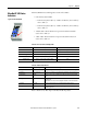
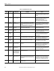
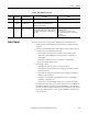
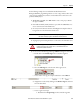
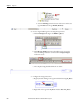
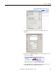
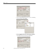
Table Of Contents
- ArmorStart Distributed Motor Controller with EtherNet/IP User Manual
- European Communities (EC) Directive Compliance
- Table of Contents
- Chapter 1
- Product Overview
- Introduction
- Description
- Catalog Number Explanation
- Operation
- Mode of Operation
- Description of Features
- Embedded Switch Technology
- Switched vs. Unswitched Control Power Input/Output (I/O) Connections
- EtherNet/IP™ Ports
- Embedded Web Server
- EtherNet/IP LED Status Indication
- Control Module LED Status and Reset
- Electronic Data Sheet (EDS)
- Fault Diagnostics
- Standard Features
- Factory-Installed Options
- Optional HOA Keypad Configuration (Bulletin 280E/281E only)
- Optional HOA Selector Keypad with Jog Function (Bulletin 284E only)
- Source Brake Contactor and Connector (Bulletin 284E only)
- EMI Filter (Bulletin 284E only)
- Dynamic Brake Connector (Bulletin 284E only)
- IP67 Dynamic Brake Resistor (Bulletin 284E only)
- Output Contactor (Bulletin 284E only)
- Shielded Motor Cable (Bulletin 284E only)
- ArmorStart® EtherNet/ IP Features
- Notes:
- Product Overview
- Chapter 2
- Installation and Wiring
- Receiving
- Unpacking
- Inspecting
- Storing
- General Precautions
- Precautions for Bulletin 280E/281E Applications
- Precautions for Bulletin 284E Applications
- Dimensions
- Mount Orientation
- Operation
- Wiring
- Terminal Designations
- Control Power Wiring
- ArmorStart with EtherNet/IP Internal Wiring
- AC Supply Considerations for Bulletin 284E Units
- Electromagnetic Compatibility (EMC)
- Grounding
- ArmorConnect Power Media
- ArmorConnect Connections
- ArmorConnect Cable Ratings
- Ethernet and I/O Connections
- Power Connections
- Optional Locking Clip
- Installation and Wiring
- Chapter 3
- Chapter 4
- Chapter 5
- Chapter 6
- Chapter 7
- Bulletin 280E/281E/284E Programmable Parameters
- Basic Setup Parameters
- Parameter Groups
- ArmorStart EtherNet/IP Parameters
- Bulletin 280E/281E
- Bulletin 284E
- Basic Status Group
- Produced Assembly Config Group
- Starter Protection Group
- User I/O Configuration Group
- Miscellaneous Configuration Group
- Drive I/O Configuration Group (Bulletin 284E only)
- Drive Display Group (Bulletin 284E only)
- Drive Setup Group (Bulletin 284E only)
- Drive Advanced Setup Group (Bulletin 284E only)
- Clear a Type 1 Fault and Restart the Drive
- Clear an Overvoltage, Undervoltage, or Heatsink OvrTmp Fault without Restarting the Drive
- How StepLogic Works
- StepLogic Settings
- Linear List of Parameters for Bulletin 280E/281E and Bulletin 284E
- Bulletin 280E/281E/284E Programmable Parameters
- Chapter 8
- Chapter 9
- Chapter 10
- Chapter 11
- Chapter 12
- Appendix A
- Applying More Than One ArmorStart Motor Controller in a Single Branch Circuit on Industrial Machinery
- Introduction
- ArmorStart LT Product Family
- Multiple-Motor Branch Circuits and Motor Controllers Listed for Group Installation – General
- Maximum Fuse Ampere Rating According to 7.2.10.4(1) and 7.2.10.4(2)
- Explanatory Example
- Input and Output Conductors of Bulletin 290E and 291E Controllers (a)
- Input and Output Conductors of Bulletin 294E Controllers (b)
- Combined Load Conductors (c)
- Applying More Than One ArmorStart Motor Controller in a Single Branch Circuit on Industrial Machinery
- Appendix B
- CIP Information
- High Level Product Description
- CIP Explicit Connection Behavior
- CIP Object Requirements
- Identity Object
- Assembly Object
- Connection Manager Object
- Discrete Input Point Object
- Discrete Output Point Object
- Parameter Object
- Parameter Group Object
- Discrete Input Group Object
- Discrete Output Group Object
- Control Supervisor Object
- Overload Object
- Device Level Ring (DLR) Object
- Qos Object
- DPI Fault Object
- DPI Alarm Object
- Interface Object
- TCP/IP Interface Object
- Ethernet Link Object
- CIP Information
- Appendix C
- Using DeviceLogix
- DeviceLogix Programming
- DeviceLogix Programming Example
- Import and Export
- Bulletin 284 - VFD Preset Speed Example
- DeviceLogix Ladder Editor Example
- ArmorStart 280 and 281 Status Bits
- Bulletin 280 and 281 ArmorStart Fault Bits
- Bulletin 280 and 281 ArmorStart Outputs
- Bulletin 280 and 281 ArmorStart Produced Network Bits
- Bulletin 284 ArmorStart Status Bits
- Bulletin 284 ArmorStart Fault Bits
- Bulletin 284 ArmorStart Outputs
- Bulletin 284 ArmorStart Produced Network Bits
- Using DeviceLogix
- Appendix D
- Appendix E
- Appendix F
- Back Cover
216 Rockwell Automation Publication 280E-UM001B-EN-P - July 2012
Chapter 9 Diagnostics
Resetting Device to
Factory Defaults
To factory reset the base and control module refer to parameter 47 “Set to
Defaults”. To reset only the VFD in the control module for Bulletin 284 refer to
Parameter 141 “Reset To Defaults”. Both these resets are limited and do not put
the product completely in the “out of box” configuration. The Type 1 Reset will
perform a full product reset to the “out of box” status.
You will need to perform a Type 1 Reset in the event that the login and password
for the product is lost and forgotten.
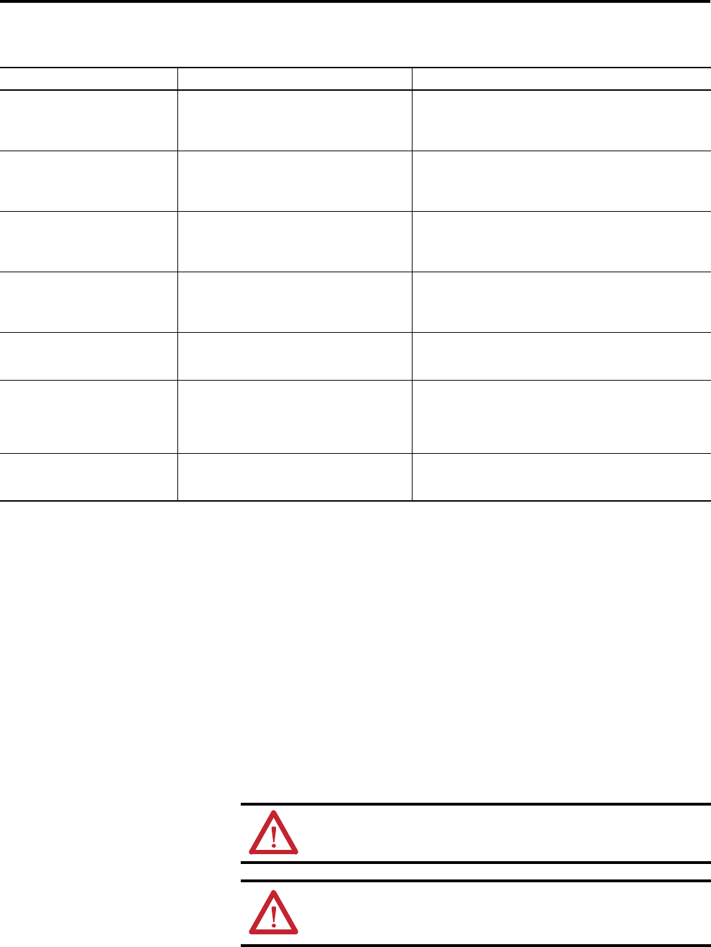
Parameter 61 Fault Code Description Recommended Action
13 = Control Power Loss Control power was lost or dipped below the lower
threshold long enough to cause the Internal Comm. fault.
• Check that control power is turned on and within specified tolerances.
• Check the Control Power fuse, replace if necessary.
• Press the local reset or send the unit a network reset once control power
is restored.
14 = Control Power Fuse The control power fuse has blown and the control power
circuit no longer is a closed circuit.
• Additional investigation as to why the fuse blew is needed. Take
corrective action accordingly.
• Replace the fuse and reset the ArmorStart either locally or over the
network.
21 = A3 Power Loss Unswitched (A3/A2) control power was lost or dipped
below the lower threshold long enough to cause the
Internal Comm. fault.
• DeviceNet power loss
• Check that the A3 or DNet power terminal does not have any loose
connections.
• Press the local reset or send the unit a network reset once the
unswitched control power is restored
22 = Internal Comm
24 = Power Loss (3-Phase)
25 = Under Voltage (3-Phase)
• The ArmorStart's MCB lost communications with the
VFD. This is most likely due to a loss of 3-phase power.
• PF Fault Code 3 or 4
• Check that the local disconnect is in the ON position.
• Check for a power quality issue, take appropriate corrective actions.
• Check that 3-phase power is present.
• Press the local reset or send the unit anetwork reset
23 = Drive Comm Loss (PF Fault Code 81) The PowerFlex VFD lost communications with the MCB.
This is most likely due to a loss of control power or
network power.
• Check that control power and the network power are both present.
• Press the local reset or send the unit a network reset.
28 = Base EEPROM The MCB can't read the base module's EEPROM or isn't
communicating correctly with the base module. In the
EtherNet/IP units, Parameter 63 – Base Trip provides
more detail as to why the base module may not be
communicating properly with the control module
• Cycle power to the ArmorStart unit.
• Ensure that the control module is seated correctly in the base module
• Check the connector on the control module for bent or broken pins
41 = DB1 Comm The MCB has lost communications with the Dynamic
Brake (DB1) board or the EEPROM on the DB1 board may
be corrupt.
• Press the local reset or send the unit a network reset
• Cycle power to the ArmorStart unit.
WARNING: A Type 1 Reset will cause all parameters and web page login to revert to
their factory defaults. No user date will be saved.
WARNING: A Type 1 Reset should only be executed when necessary or when the login
and password must be cleared and set to the factory default setting.
SERVICE CODE 0X05
Class Code 0x0001
INSTANCE 1
Data (USINT) 1