
User Manual Owner's manual
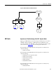
Table Of Contents
- ArmorStart Distributed Motor Controller with EtherNet/IP User Manual
- European Communities (EC) Directive Compliance
- Table of Contents
- Chapter 1
- Product Overview
- Introduction
- Description
- Catalog Number Explanation
- Operation
- Mode of Operation
- Description of Features
- Embedded Switch Technology
- Switched vs. Unswitched Control Power Input/Output (I/O) Connections
- EtherNet/IP™ Ports
- Embedded Web Server
- EtherNet/IP LED Status Indication
- Control Module LED Status and Reset
- Electronic Data Sheet (EDS)
- Fault Diagnostics
- Standard Features
- Factory-Installed Options
- Optional HOA Keypad Configuration (Bulletin 280E/281E only)
- Optional HOA Selector Keypad with Jog Function (Bulletin 284E only)
- Source Brake Contactor and Connector (Bulletin 284E only)
- EMI Filter (Bulletin 284E only)
- Dynamic Brake Connector (Bulletin 284E only)
- IP67 Dynamic Brake Resistor (Bulletin 284E only)
- Output Contactor (Bulletin 284E only)
- Shielded Motor Cable (Bulletin 284E only)
- ArmorStart® EtherNet/ IP Features
- Notes:
- Product Overview
- Chapter 2
- Installation and Wiring
- Receiving
- Unpacking
- Inspecting
- Storing
- General Precautions
- Precautions for Bulletin 280E/281E Applications
- Precautions for Bulletin 284E Applications
- Dimensions
- Mount Orientation
- Operation
- Wiring
- Terminal Designations
- Control Power Wiring
- ArmorStart with EtherNet/IP Internal Wiring
- AC Supply Considerations for Bulletin 284E Units
- Electromagnetic Compatibility (EMC)
- Grounding
- ArmorConnect Power Media
- ArmorConnect Connections
- ArmorConnect Cable Ratings
- Ethernet and I/O Connections
- Power Connections
- Optional Locking Clip
- Installation and Wiring
- Chapter 3
- Chapter 4
- Chapter 5
- Chapter 6
- Chapter 7
- Bulletin 280E/281E/284E Programmable Parameters
- Basic Setup Parameters
- Parameter Groups
- ArmorStart EtherNet/IP Parameters
- Bulletin 280E/281E
- Bulletin 284E
- Basic Status Group
- Produced Assembly Config Group
- Starter Protection Group
- User I/O Configuration Group
- Miscellaneous Configuration Group
- Drive I/O Configuration Group (Bulletin 284E only)
- Drive Display Group (Bulletin 284E only)
- Drive Setup Group (Bulletin 284E only)
- Drive Advanced Setup Group (Bulletin 284E only)
- Clear a Type 1 Fault and Restart the Drive
- Clear an Overvoltage, Undervoltage, or Heatsink OvrTmp Fault without Restarting the Drive
- How StepLogic Works
- StepLogic Settings
- Linear List of Parameters for Bulletin 280E/281E and Bulletin 284E
- Bulletin 280E/281E/284E Programmable Parameters
- Chapter 8
- Chapter 9
- Chapter 10
- Chapter 11
- Chapter 12
- Appendix A
- Applying More Than One ArmorStart Motor Controller in a Single Branch Circuit on Industrial Machinery
- Introduction
- ArmorStart LT Product Family
- Multiple-Motor Branch Circuits and Motor Controllers Listed for Group Installation – General
- Maximum Fuse Ampere Rating According to 7.2.10.4(1) and 7.2.10.4(2)
- Explanatory Example
- Input and Output Conductors of Bulletin 290E and 291E Controllers (a)
- Input and Output Conductors of Bulletin 294E Controllers (b)
- Combined Load Conductors (c)
- Applying More Than One ArmorStart Motor Controller in a Single Branch Circuit on Industrial Machinery
- Appendix B
- CIP Information
- High Level Product Description
- CIP Explicit Connection Behavior
- CIP Object Requirements
- Identity Object
- Assembly Object
- Connection Manager Object
- Discrete Input Point Object
- Discrete Output Point Object
- Parameter Object
- Parameter Group Object
- Discrete Input Group Object
- Discrete Output Group Object
- Control Supervisor Object
- Overload Object
- Device Level Ring (DLR) Object
- Qos Object
- DPI Fault Object
- DPI Alarm Object
- Interface Object
- TCP/IP Interface Object
- Ethernet Link Object
- CIP Information
- Appendix C
- Using DeviceLogix
- DeviceLogix Programming
- DeviceLogix Programming Example
- Import and Export
- Bulletin 284 - VFD Preset Speed Example
- DeviceLogix Ladder Editor Example
- ArmorStart 280 and 281 Status Bits
- Bulletin 280 and 281 ArmorStart Fault Bits
- Bulletin 280 and 281 ArmorStart Outputs
- Bulletin 280 and 281 ArmorStart Produced Network Bits
- Bulletin 284 ArmorStart Status Bits
- Bulletin 284 ArmorStart Fault Bits
- Bulletin 284 ArmorStart Outputs
- Bulletin 284 ArmorStart Produced Network Bits
- Using DeviceLogix
- Appendix D
- Appendix E
- Appendix F
- Back Cover

Rockwell Automation Publication 280E-UM001B-EN-P - July 2012 227
Troubleshooting Chapter 10
higher than expected. This fault is disabled when Parameter 182 (DB1 Resistor
Sel) is “Disabled”.
Troubleshooting – DB1 monitor has measured a DB1 current lower than
expected. Turn off all power to unit. Allow at least 3 minutes for capacitors to
discharge. Disconnect DB1 resistor from ArmorStart control module. Caution:
DB1 resistor may still be hot. Measure DB1 resistor value at the connector
with an ohmmeter. Refer to the specification for minimum DB1 resistor values.
If DB1 resistance value is within limits, replace control module. If not, replace
DB1 resistor.
DB1 Switch Fault
Control Supervisor Object “DB1 Fault” Attribute Bit 3.
A DB1 Switch fault is issued when continuous DB1 resistor current is detected
when the Drive Bus Voltage level is less than the DB1 Voltage Level. If 5
consecutive samples of Drive Bus Voltage less than DB1 Level is detected along
with continuous DB1 resistor current flow, then a shorted DB1 IGBT fault
(DB1 Switch) is recorded.
It is the user’s responsibility to provide an input power contactor to each
ArmorStart with a drive. The user must write logic to control (open) the input
contactor to the ArmorStart in the event of a DB1 Switch Fault. The Instruction
Literature provides information on how to connect the input contactor, and how
to implement the logic.
Troubleshooting – Attempt to reset the fault by removing all power to the unit
and restarting. If the fault persists, replace control module.
DB1 Open Fault
Control Supervisor Object “DB1 Fault” Attribute Bit 4.
A DB1 Open fault is issued when Bus Voltage is greater than the DB1 Voltage
Level, and no DB1 resistor current has been detected. If 5 consecutive samples
of Drive Bus Voltage greater than the DB1 Level is detected along with no DB1
resistor current flow, then an open DB1 fault is recorded. This fault is intended
to notify the customer of an open DB1 resistor, or open wire. The fault is disabled
when the DB1 Resistor Sel, Parameter (182) is “Disabled”.
Troubleshooting – DB1 monitor expected to see current flow and measured
none. Likely cause is an open DB1 resistor, loose DB1 resistor connector, or open
wire in DB1 cable. Check DB1 cable connector for tightness. If problem persists,
remove DB1 resistor cable connector from unit and check DB1 resistance. If
DB1 resistor is open, replace DB1 resistor. Otherwise replace control module.