
User Manual Owner's manual
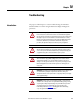
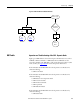
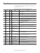
Table Of Contents
- ArmorStart Distributed Motor Controller with EtherNet/IP User Manual
- European Communities (EC) Directive Compliance
- Table of Contents
- Chapter 1
- Product Overview
- Introduction
- Description
- Catalog Number Explanation
- Operation
- Mode of Operation
- Description of Features
- Embedded Switch Technology
- Switched vs. Unswitched Control Power Input/Output (I/O) Connections
- EtherNet/IP™ Ports
- Embedded Web Server
- EtherNet/IP LED Status Indication
- Control Module LED Status and Reset
- Electronic Data Sheet (EDS)
- Fault Diagnostics
- Standard Features
- Factory-Installed Options
- Optional HOA Keypad Configuration (Bulletin 280E/281E only)
- Optional HOA Selector Keypad with Jog Function (Bulletin 284E only)
- Source Brake Contactor and Connector (Bulletin 284E only)
- EMI Filter (Bulletin 284E only)
- Dynamic Brake Connector (Bulletin 284E only)
- IP67 Dynamic Brake Resistor (Bulletin 284E only)
- Output Contactor (Bulletin 284E only)
- Shielded Motor Cable (Bulletin 284E only)
- ArmorStart® EtherNet/ IP Features
- Notes:
- Product Overview
- Chapter 2
- Installation and Wiring
- Receiving
- Unpacking
- Inspecting
- Storing
- General Precautions
- Precautions for Bulletin 280E/281E Applications
- Precautions for Bulletin 284E Applications
- Dimensions
- Mount Orientation
- Operation
- Wiring
- Terminal Designations
- Control Power Wiring
- ArmorStart with EtherNet/IP Internal Wiring
- AC Supply Considerations for Bulletin 284E Units
- Electromagnetic Compatibility (EMC)
- Grounding
- ArmorConnect Power Media
- ArmorConnect Connections
- ArmorConnect Cable Ratings
- Ethernet and I/O Connections
- Power Connections
- Optional Locking Clip
- Installation and Wiring
- Chapter 3
- Chapter 4
- Chapter 5
- Chapter 6
- Chapter 7
- Bulletin 280E/281E/284E Programmable Parameters
- Basic Setup Parameters
- Parameter Groups
- ArmorStart EtherNet/IP Parameters
- Bulletin 280E/281E
- Bulletin 284E
- Basic Status Group
- Produced Assembly Config Group
- Starter Protection Group
- User I/O Configuration Group
- Miscellaneous Configuration Group
- Drive I/O Configuration Group (Bulletin 284E only)
- Drive Display Group (Bulletin 284E only)
- Drive Setup Group (Bulletin 284E only)
- Drive Advanced Setup Group (Bulletin 284E only)
- Clear a Type 1 Fault and Restart the Drive
- Clear an Overvoltage, Undervoltage, or Heatsink OvrTmp Fault without Restarting the Drive
- How StepLogic Works
- StepLogic Settings
- Linear List of Parameters for Bulletin 280E/281E and Bulletin 284E
- Bulletin 280E/281E/284E Programmable Parameters
- Chapter 8
- Chapter 9
- Chapter 10
- Chapter 11
- Chapter 12
- Appendix A
- Applying More Than One ArmorStart Motor Controller in a Single Branch Circuit on Industrial Machinery
- Introduction
- ArmorStart LT Product Family
- Multiple-Motor Branch Circuits and Motor Controllers Listed for Group Installation – General
- Maximum Fuse Ampere Rating According to 7.2.10.4(1) and 7.2.10.4(2)
- Explanatory Example
- Input and Output Conductors of Bulletin 290E and 291E Controllers (a)
- Input and Output Conductors of Bulletin 294E Controllers (b)
- Combined Load Conductors (c)
- Applying More Than One ArmorStart Motor Controller in a Single Branch Circuit on Industrial Machinery
- Appendix B
- CIP Information
- High Level Product Description
- CIP Explicit Connection Behavior
- CIP Object Requirements
- Identity Object
- Assembly Object
- Connection Manager Object
- Discrete Input Point Object
- Discrete Output Point Object
- Parameter Object
- Parameter Group Object
- Discrete Input Group Object
- Discrete Output Group Object
- Control Supervisor Object
- Overload Object
- Device Level Ring (DLR) Object
- Qos Object
- DPI Fault Object
- DPI Alarm Object
- Interface Object
- TCP/IP Interface Object
- Ethernet Link Object
- CIP Information
- Appendix C
- Using DeviceLogix
- DeviceLogix Programming
- DeviceLogix Programming Example
- Import and Export
- Bulletin 284 - VFD Preset Speed Example
- DeviceLogix Ladder Editor Example
- ArmorStart 280 and 281 Status Bits
- Bulletin 280 and 281 ArmorStart Fault Bits
- Bulletin 280 and 281 ArmorStart Outputs
- Bulletin 280 and 281 ArmorStart Produced Network Bits
- Bulletin 284 ArmorStart Status Bits
- Bulletin 284 ArmorStart Fault Bits
- Bulletin 284 ArmorStart Outputs
- Bulletin 284 ArmorStart Produced Network Bits
- Using DeviceLogix
- Appendix D
- Appendix E
- Appendix F
- Back Cover

230 Rockwell Automation Publication 280E-UM001B-EN-P - July 2012
Chapter 10 Troubleshooting
The following table describes Bulletin 284E Faults as seen in Parameters 107,
108, and 109 (Fault 1, 2 or 3).
Table 39 - Bulletin 284E Faults – Parameters 107, 108, and 109 (Fault 1, 2 or 3)
No. Fault
Type
➊ Description Action
F2 Auxiliary Input 1 Auxiliary input interlock is open. 4. Check remote wiring.
5. Verify communications.
F3 Power Loss 2 DC bus voltage remained below 85% of
nominal.
6. Monitor the incoming AC line for low voltage or line power interruption.
7. Check input fuses.
F4 UnderVoltage 1 DC bus voltage fell below the minimum
value.
8. Monitor the incoming AC line for low voltage or line power interruption.
F5 OverVoltage 1 DC bus voltage exceeded maximum
value.
9. Monitor the AC line for high line voltage or transient conditions. Bus overvoltage can also
be caused by motor regeneration. Extend the decel time or install dynamic brake option.
F6 Motor Stalled 1 Drive is unable to accelerate motor. 10. Increase Parameters 139 or 167 (Accel Time x) or reduce load so drive output current does
not exceed the current set by Parameter 189 (Current Limit 1).
F7 Motor Overload 1 Internal electronic overload trip 11. An excessive motor load exists. Reduce load so drive output current does not exceed the
current set by Parameter 133 (Motor OL Current).
12. Verify Parameter 184 (Boost Select) setting
F8 Heatsink OvrTmp 1 Heatsink temperature exceeds a
predefined value.
13. Check for blocked or dirty heat sink fins. Verify that ambient temperature has not
exceeded 40°C.
14. Replace internal fan.
F12 HW OverCurrent 2 The drive output current has exceeded
the hardware current limit.
15. Check programming. Check for excess load, improper programming of Parameter 184
(Boost Select), DC brake volts set too high, or other causes of excess current.
F13 Ground Fault 2 A current path to earth ground has been
detected at one or more of the drive
output terminals.
16. Check the motor and external wiring to the drive output terminals for a grounded
condition.
F33 Auto Rstrt Tries Drive unsuccessfully attempted to reset a
fault and resume running for the
programmed number of Parameter 192
(Auto Rstrt Tries).
17. Correct the cause of the fault and manually clear.
F38
F39
F40
Phase U to Gnd
Phase V to Gnd
Phase W to Gnd
2 A phase to ground fault has been
detected between the drive and motor in
this phase.
18. Check the wiring between the drive and motor.
19. Check motor for grounded phase.
20. Replace starter module if fault cannot be cleared.
F41
F42
F43
Phase UV Short
Phase UW Short
Phase VW Short
2 Excessive current has been detected
between these two output terminals.
21. Check the motor and drive output terminal wiring for a shorted condition.
22. Replace starter module if fault cannot be cleared.
F48 Params Defaulted 2 The drive was commanded to write
default values to EEPROM.
23. Clear the fault or cycle power to the drive.
24. Program the drive parameters as needed.
F63 SW OverCurrent 2 Programmed Parameter 198 (SW Current
Trip) has been exceeded.
25. Check load requirements and Parameter 198 (SW Current Trip) setting.
F64 Drive Overload 2 Drive rating of 150% for 1 min. or 200%
for 3 sec. has been exceeded.
26. Reduce load or extend Accel Time.
F70 Power Unit 2 Failure has been detected in the drive
power section.
27. Cycle power.
28. Replace starter module if fault cannot be cleared.
F80 SVC Autotune The autotune function was either
cancelled by the user or failed.
29. Restart procedure.