
User Manual Owner's manual
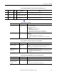
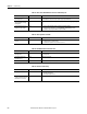
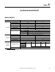
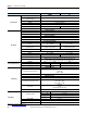
Table Of Contents
- ArmorStart Distributed Motor Controller with EtherNet/IP User Manual
- European Communities (EC) Directive Compliance
- Table of Contents
- Chapter 1
- Product Overview
- Introduction
- Description
- Catalog Number Explanation
- Operation
- Mode of Operation
- Description of Features
- Embedded Switch Technology
- Switched vs. Unswitched Control Power Input/Output (I/O) Connections
- EtherNet/IP™ Ports
- Embedded Web Server
- EtherNet/IP LED Status Indication
- Control Module LED Status and Reset
- Electronic Data Sheet (EDS)
- Fault Diagnostics
- Standard Features
- Factory-Installed Options
- Optional HOA Keypad Configuration (Bulletin 280E/281E only)
- Optional HOA Selector Keypad with Jog Function (Bulletin 284E only)
- Source Brake Contactor and Connector (Bulletin 284E only)
- EMI Filter (Bulletin 284E only)
- Dynamic Brake Connector (Bulletin 284E only)
- IP67 Dynamic Brake Resistor (Bulletin 284E only)
- Output Contactor (Bulletin 284E only)
- Shielded Motor Cable (Bulletin 284E only)
- ArmorStart® EtherNet/ IP Features
- Notes:
- Product Overview
- Chapter 2
- Installation and Wiring
- Receiving
- Unpacking
- Inspecting
- Storing
- General Precautions
- Precautions for Bulletin 280E/281E Applications
- Precautions for Bulletin 284E Applications
- Dimensions
- Mount Orientation
- Operation
- Wiring
- Terminal Designations
- Control Power Wiring
- ArmorStart with EtherNet/IP Internal Wiring
- AC Supply Considerations for Bulletin 284E Units
- Electromagnetic Compatibility (EMC)
- Grounding
- ArmorConnect Power Media
- ArmorConnect Connections
- ArmorConnect Cable Ratings
- Ethernet and I/O Connections
- Power Connections
- Optional Locking Clip
- Installation and Wiring
- Chapter 3
- Chapter 4
- Chapter 5
- Chapter 6
- Chapter 7
- Bulletin 280E/281E/284E Programmable Parameters
- Basic Setup Parameters
- Parameter Groups
- ArmorStart EtherNet/IP Parameters
- Bulletin 280E/281E
- Bulletin 284E
- Basic Status Group
- Produced Assembly Config Group
- Starter Protection Group
- User I/O Configuration Group
- Miscellaneous Configuration Group
- Drive I/O Configuration Group (Bulletin 284E only)
- Drive Display Group (Bulletin 284E only)
- Drive Setup Group (Bulletin 284E only)
- Drive Advanced Setup Group (Bulletin 284E only)
- Clear a Type 1 Fault and Restart the Drive
- Clear an Overvoltage, Undervoltage, or Heatsink OvrTmp Fault without Restarting the Drive
- How StepLogic Works
- StepLogic Settings
- Linear List of Parameters for Bulletin 280E/281E and Bulletin 284E
- Bulletin 280E/281E/284E Programmable Parameters
- Chapter 8
- Chapter 9
- Chapter 10
- Chapter 11
- Chapter 12
- Appendix A
- Applying More Than One ArmorStart Motor Controller in a Single Branch Circuit on Industrial Machinery
- Introduction
- ArmorStart LT Product Family
- Multiple-Motor Branch Circuits and Motor Controllers Listed for Group Installation – General
- Maximum Fuse Ampere Rating According to 7.2.10.4(1) and 7.2.10.4(2)
- Explanatory Example
- Input and Output Conductors of Bulletin 290E and 291E Controllers (a)
- Input and Output Conductors of Bulletin 294E Controllers (b)
- Combined Load Conductors (c)
- Applying More Than One ArmorStart Motor Controller in a Single Branch Circuit on Industrial Machinery
- Appendix B
- CIP Information
- High Level Product Description
- CIP Explicit Connection Behavior
- CIP Object Requirements
- Identity Object
- Assembly Object
- Connection Manager Object
- Discrete Input Point Object
- Discrete Output Point Object
- Parameter Object
- Parameter Group Object
- Discrete Input Group Object
- Discrete Output Group Object
- Control Supervisor Object
- Overload Object
- Device Level Ring (DLR) Object
- Qos Object
- DPI Fault Object
- DPI Alarm Object
- Interface Object
- TCP/IP Interface Object
- Ethernet Link Object
- CIP Information
- Appendix C
- Using DeviceLogix
- DeviceLogix Programming
- DeviceLogix Programming Example
- Import and Export
- Bulletin 284 - VFD Preset Speed Example
- DeviceLogix Ladder Editor Example
- ArmorStart 280 and 281 Status Bits
- Bulletin 280 and 281 ArmorStart Fault Bits
- Bulletin 280 and 281 ArmorStart Outputs
- Bulletin 280 and 281 ArmorStart Produced Network Bits
- Bulletin 284 ArmorStart Status Bits
- Bulletin 284 ArmorStart Fault Bits
- Bulletin 284 ArmorStart Outputs
- Bulletin 284 ArmorStart Produced Network Bits
- Using DeviceLogix
- Appendix D
- Appendix E
- Appendix F
- Back Cover

Rockwell Automation Publication 280E-UM001B-EN-P - July 2012 231
Troubleshooting Chapter 10
➊ See Table 38 for Type description.
F81 Comm Loss 2 RS485 (DSI) port stopped
communicating.
30. Turn off using Parameter 205 (Comm Loss Action).
31. Replace starter module if fault cannot be cleared.
F100 Parameter
Checksum
2 The checksum read from the board does
not match the checksum calculated.
32. Set Parameter 141 (Reset To Defaults) to Option 1 (Reset Defaults).
F122 I/O Board Fail 2 Failure has been detected in the drive
control and I/O section.
33. Cycle power.
34. Replace starter module if fault cannot be cleared.
Table 39 - Bulletin 284E Faults – Parameters 107, 108, and 109 (Fault 1, 2 or 3)
No. Fault
Type
➊ Description Action
Table 40 - Motor Does Not Start
Cause(s) Indication Corrective Action
No output voltage to the motor. None Check the power circuit.
• Check the supply voltage.
• Check all fuses and disconnects
Check the motor.
• Verify that the motor is connected properly.
• Verify that I/O Terminal 01 is active.
• Verify that Parameter 136 (Start Source) matches your configuration.
• Verify that Parameter 195 (Reverse Disable) is not prohibiting movement.
Drive is Faulted Flashing red status light Clear fault.
• Press Stop
• Cycle power
• Set Parameter 200 (Fault Clear) to Option 1 (Clear Faults).
• Cycle digital input is Parameters 151…154 (Digital In x Sel) is set to Option 7, (Clear
Faults).
Table 41 - Drive Does Not Respond to Changes in Speed Command
Cause(s) Indication Corrective Action
No value is coming form the
source of the command.
The drive Run indicator is lit
and output is 0 Hz.
• Check Parameter 112 (Control Source) for correct source.
• If the source is an analog input, check wiring and use a meter to check for presence of
signal.
• Check Parameter 102 (Commanded Freq) to verify correct command.
Incorrect reference source is
being selected via remote device
or digital inputs.
None • Check Parameter 112 (Control Source) for correct source.
• Check Parameter 114 (Dig In Status) to see if inputs are selecting an alternate source. Verify
settings for Parameters 151…154 (Digital In x Sel).
• Check Parameter 138 (Speed Reference) for the source of the speed reference. Reprogram
as necessary.
Table 42 - Motor and/or Drive Will Not Accelerate to Commanded Speed
Cause(s) Indication Corrective Action
Acceleration time is excessive. None Reprogram Parameter 139 (Accel Time 1) or Parameter 167 (Accel Time 2).
Excess load or short acceleration
times force the drive into current
limit, slowing, or stopping
acceleration.
None • Compare Parameter 103 (Output Current) with Parameter 189 (Current Limit1).
• Remove excess load or reprogram Parameter 139 (Accel Time 1) or Parameter 167 (Accel
Time 2).
• Check for improper setting of Parameter 184 (Boost Select).