
User Manual Owner's manual
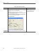
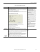
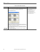
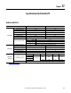
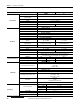
Table Of Contents
- ArmorStart Distributed Motor Controller with EtherNet/IP User Manual
- European Communities (EC) Directive Compliance
- Table of Contents
- Chapter 1
- Product Overview
- Introduction
- Description
- Catalog Number Explanation
- Operation
- Mode of Operation
- Description of Features
- Embedded Switch Technology
- Switched vs. Unswitched Control Power Input/Output (I/O) Connections
- EtherNet/IP™ Ports
- Embedded Web Server
- EtherNet/IP LED Status Indication
- Control Module LED Status and Reset
- Electronic Data Sheet (EDS)
- Fault Diagnostics
- Standard Features
- Factory-Installed Options
- Optional HOA Keypad Configuration (Bulletin 280E/281E only)
- Optional HOA Selector Keypad with Jog Function (Bulletin 284E only)
- Source Brake Contactor and Connector (Bulletin 284E only)
- EMI Filter (Bulletin 284E only)
- Dynamic Brake Connector (Bulletin 284E only)
- IP67 Dynamic Brake Resistor (Bulletin 284E only)
- Output Contactor (Bulletin 284E only)
- Shielded Motor Cable (Bulletin 284E only)
- ArmorStart® EtherNet/ IP Features
- Notes:
- Product Overview
- Chapter 2
- Installation and Wiring
- Receiving
- Unpacking
- Inspecting
- Storing
- General Precautions
- Precautions for Bulletin 280E/281E Applications
- Precautions for Bulletin 284E Applications
- Dimensions
- Mount Orientation
- Operation
- Wiring
- Terminal Designations
- Control Power Wiring
- ArmorStart with EtherNet/IP Internal Wiring
- AC Supply Considerations for Bulletin 284E Units
- Electromagnetic Compatibility (EMC)
- Grounding
- ArmorConnect Power Media
- ArmorConnect Connections
- ArmorConnect Cable Ratings
- Ethernet and I/O Connections
- Power Connections
- Optional Locking Clip
- Installation and Wiring
- Chapter 3
- Chapter 4
- Chapter 5
- Chapter 6
- Chapter 7
- Bulletin 280E/281E/284E Programmable Parameters
- Basic Setup Parameters
- Parameter Groups
- ArmorStart EtherNet/IP Parameters
- Bulletin 280E/281E
- Bulletin 284E
- Basic Status Group
- Produced Assembly Config Group
- Starter Protection Group
- User I/O Configuration Group
- Miscellaneous Configuration Group
- Drive I/O Configuration Group (Bulletin 284E only)
- Drive Display Group (Bulletin 284E only)
- Drive Setup Group (Bulletin 284E only)
- Drive Advanced Setup Group (Bulletin 284E only)
- Clear a Type 1 Fault and Restart the Drive
- Clear an Overvoltage, Undervoltage, or Heatsink OvrTmp Fault without Restarting the Drive
- How StepLogic Works
- StepLogic Settings
- Linear List of Parameters for Bulletin 280E/281E and Bulletin 284E
- Bulletin 280E/281E/284E Programmable Parameters
- Chapter 8
- Chapter 9
- Chapter 10
- Chapter 11
- Chapter 12
- Appendix A
- Applying More Than One ArmorStart Motor Controller in a Single Branch Circuit on Industrial Machinery
- Introduction
- ArmorStart LT Product Family
- Multiple-Motor Branch Circuits and Motor Controllers Listed for Group Installation – General
- Maximum Fuse Ampere Rating According to 7.2.10.4(1) and 7.2.10.4(2)
- Explanatory Example
- Input and Output Conductors of Bulletin 290E and 291E Controllers (a)
- Input and Output Conductors of Bulletin 294E Controllers (b)
- Combined Load Conductors (c)
- Applying More Than One ArmorStart Motor Controller in a Single Branch Circuit on Industrial Machinery
- Appendix B
- CIP Information
- High Level Product Description
- CIP Explicit Connection Behavior
- CIP Object Requirements
- Identity Object
- Assembly Object
- Connection Manager Object
- Discrete Input Point Object
- Discrete Output Point Object
- Parameter Object
- Parameter Group Object
- Discrete Input Group Object
- Discrete Output Group Object
- Control Supervisor Object
- Overload Object
- Device Level Ring (DLR) Object
- Qos Object
- DPI Fault Object
- DPI Alarm Object
- Interface Object
- TCP/IP Interface Object
- Ethernet Link Object
- CIP Information
- Appendix C
- Using DeviceLogix
- DeviceLogix Programming
- DeviceLogix Programming Example
- Import and Export
- Bulletin 284 - VFD Preset Speed Example
- DeviceLogix Ladder Editor Example
- ArmorStart 280 and 281 Status Bits
- Bulletin 280 and 281 ArmorStart Fault Bits
- Bulletin 280 and 281 ArmorStart Outputs
- Bulletin 280 and 281 ArmorStart Produced Network Bits
- Bulletin 284 ArmorStart Status Bits
- Bulletin 284 ArmorStart Fault Bits
- Bulletin 284 ArmorStart Outputs
- Bulletin 284 ArmorStart Produced Network Bits
- Using DeviceLogix
- Appendix D
- Appendix E
- Appendix F
- Back Cover

Rockwell Automation Publication 280E-UM001B-EN-P - July 2012 237
Troubleshooting Chapter 10
Rapid Ring Fault
When a Rapid Ring Fault occurs, the following events occur:
• The active supervisor will block traffic on port 2, resulting in possible network segmentation, that is,
some nodes may become unreachable.
• The Link 2 status indicator on the active supervisor is off.
• As soon as the fault occurs, for both RSLogix 5000 programming software and RSLinx communication
software, the Status field = Rapid Fault/Restore Cycles.
Figure 88 - Rapid Fault/Restore Cycles Status
Any of the following may cause a Rapid Ring Fault:
• 5 intentional disconnections/reconnections of a node from the network within 30 s
• A duplex mismatch between two connected devices
• Electromagnetic noise on the network
• Unstable physical connections, such as intermittent connectors
Given the nature of a Rapid Ring Fault, the Last Active Node information may not be accurate when a
Rapid Ring Fault condition is present
Multiple possible solutions exist.
• For the disconnections and reconnections
issue, no solution is required.
Clear the fault when you have reconnected the
device to the network permanently.
• For the duplex mismatch issue, reconfigure the
duplex parameters to make sure they match
between the devices.
• For the electromagnetic noise issue, determine
where the noise exists and eliminate it or use a
protective shield in that location.
• For the unstable connections issue, determine
where they exist on the network and correct
them.
• Check the media counters for all devices on the
network. The device with the highest media
counter count is most likely causing the Rapid
Ring Fault.
• Remove devices from the network one by one.
When you see the Rapid Ring Fault disappear
after a device is removed, that device is
causing the fault.
• Finally, your Beacon Interval or Timeout
configuration may not be appropriate for your
network.
However, if you think you need to change
these values, we recommend that you call
Rockwell Automation technical support.
Once the fault is fixed, click Clear Fault.
Partial Fault
Condition
A partial network fault occurs when traffic is lost in only one direction on the network because a ring
member is not forwarding beacons in both directions for some reason, such as because of a component
failure.
The active ring supervisor detects a partial fault by monitoring the loss of Beacon frames on one port
and the fault location appears in the Ring Fault section of the Network tab.
When a partial fault is detected, the active ring supervisor blocks traffic on one port. At this point, the
ring is segmented due to the partial fault condition. The nodes adjacent to the faulted part of the
network are displayed in the Ring Fault group with either IP addresses or MAC ID’s for each node
displayed.
When this fault occurs the Network Status field = Partial Fault Condition.
Once the fault is corrected, it automatically clears, and the Network Status field returns to Normal.
Determine where the fault condition exists and
correct it.
Table 46 - Troubleshoot DLR or Linear Network
Issue Description Solution