
User Manual Owner's manual
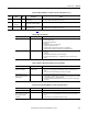
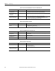
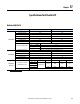
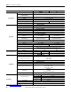
Table Of Contents
- ArmorStart Distributed Motor Controller with EtherNet/IP User Manual
- European Communities (EC) Directive Compliance
- Table of Contents
- Chapter 1
- Product Overview
- Introduction
- Description
- Catalog Number Explanation
- Operation
- Mode of Operation
- Description of Features
- Embedded Switch Technology
- Switched vs. Unswitched Control Power Input/Output (I/O) Connections
- EtherNet/IP™ Ports
- Embedded Web Server
- EtherNet/IP LED Status Indication
- Control Module LED Status and Reset
- Electronic Data Sheet (EDS)
- Fault Diagnostics
- Standard Features
- Factory-Installed Options
- Optional HOA Keypad Configuration (Bulletin 280E/281E only)
- Optional HOA Selector Keypad with Jog Function (Bulletin 284E only)
- Source Brake Contactor and Connector (Bulletin 284E only)
- EMI Filter (Bulletin 284E only)
- Dynamic Brake Connector (Bulletin 284E only)
- IP67 Dynamic Brake Resistor (Bulletin 284E only)
- Output Contactor (Bulletin 284E only)
- Shielded Motor Cable (Bulletin 284E only)
- ArmorStart® EtherNet/ IP Features
- Notes:
- Product Overview
- Chapter 2
- Installation and Wiring
- Receiving
- Unpacking
- Inspecting
- Storing
- General Precautions
- Precautions for Bulletin 280E/281E Applications
- Precautions for Bulletin 284E Applications
- Dimensions
- Mount Orientation
- Operation
- Wiring
- Terminal Designations
- Control Power Wiring
- ArmorStart with EtherNet/IP Internal Wiring
- AC Supply Considerations for Bulletin 284E Units
- Electromagnetic Compatibility (EMC)
- Grounding
- ArmorConnect Power Media
- ArmorConnect Connections
- ArmorConnect Cable Ratings
- Ethernet and I/O Connections
- Power Connections
- Optional Locking Clip
- Installation and Wiring
- Chapter 3
- Chapter 4
- Chapter 5
- Chapter 6
- Chapter 7
- Bulletin 280E/281E/284E Programmable Parameters
- Basic Setup Parameters
- Parameter Groups
- ArmorStart EtherNet/IP Parameters
- Bulletin 280E/281E
- Bulletin 284E
- Basic Status Group
- Produced Assembly Config Group
- Starter Protection Group
- User I/O Configuration Group
- Miscellaneous Configuration Group
- Drive I/O Configuration Group (Bulletin 284E only)
- Drive Display Group (Bulletin 284E only)
- Drive Setup Group (Bulletin 284E only)
- Drive Advanced Setup Group (Bulletin 284E only)
- Clear a Type 1 Fault and Restart the Drive
- Clear an Overvoltage, Undervoltage, or Heatsink OvrTmp Fault without Restarting the Drive
- How StepLogic Works
- StepLogic Settings
- Linear List of Parameters for Bulletin 280E/281E and Bulletin 284E
- Bulletin 280E/281E/284E Programmable Parameters
- Chapter 8
- Chapter 9
- Chapter 10
- Chapter 11
- Chapter 12
- Appendix A
- Applying More Than One ArmorStart Motor Controller in a Single Branch Circuit on Industrial Machinery
- Introduction
- ArmorStart LT Product Family
- Multiple-Motor Branch Circuits and Motor Controllers Listed for Group Installation – General
- Maximum Fuse Ampere Rating According to 7.2.10.4(1) and 7.2.10.4(2)
- Explanatory Example
- Input and Output Conductors of Bulletin 290E and 291E Controllers (a)
- Input and Output Conductors of Bulletin 294E Controllers (b)
- Combined Load Conductors (c)
- Applying More Than One ArmorStart Motor Controller in a Single Branch Circuit on Industrial Machinery
- Appendix B
- CIP Information
- High Level Product Description
- CIP Explicit Connection Behavior
- CIP Object Requirements
- Identity Object
- Assembly Object
- Connection Manager Object
- Discrete Input Point Object
- Discrete Output Point Object
- Parameter Object
- Parameter Group Object
- Discrete Input Group Object
- Discrete Output Group Object
- Control Supervisor Object
- Overload Object
- Device Level Ring (DLR) Object
- Qos Object
- DPI Fault Object
- DPI Alarm Object
- Interface Object
- TCP/IP Interface Object
- Ethernet Link Object
- CIP Information
- Appendix C
- Using DeviceLogix
- DeviceLogix Programming
- DeviceLogix Programming Example
- Import and Export
- Bulletin 284 - VFD Preset Speed Example
- DeviceLogix Ladder Editor Example
- ArmorStart 280 and 281 Status Bits
- Bulletin 280 and 281 ArmorStart Fault Bits
- Bulletin 280 and 281 ArmorStart Outputs
- Bulletin 280 and 281 ArmorStart Produced Network Bits
- Bulletin 284 ArmorStart Status Bits
- Bulletin 284 ArmorStart Fault Bits
- Bulletin 284 ArmorStart Outputs
- Bulletin 284 ArmorStart Produced Network Bits
- Using DeviceLogix
- Appendix D
- Appendix E
- Appendix F
- Back Cover
240 Rockwell Automation Publication 280E-UM001B-EN-P - July 2012
Chapter 11 Specifications for EtherNet/IP
UL/NEMA IEC
Environmental
Operating Temperature Range –20…40 °C (–4…104 °F)
Storage and Transportation
Temperature Range
–25….85 °C (–13…185 °F)
Altitude 1000 m
Humidity 5…95% (on-condensing)
Pollution Degree 3
Enclosure Ratings NEMA 4/12 IP67
Approximate Shipping Weight 18.1 kg (40 lbs)
Mechanical
Resistance to Shock
Operational 15 G
Non-Operational 30 G
Resistance to Vibration
Operational 1 G, 0.15 mm (0.006 in.) Displacement
Non-Operational 2.5 G, 0.38 mm (0.015 in.) Displacement
Power and Ground Terminals
Wire Size
Primary/Secondary Terminal:
#16…#10 AWG
Primary/Secondary Terminal:
1.0…4.0 mm2
Tightening Torque
Primary Terminal: 10.8 lb·in.
Secondary Terminal: 4.5 lb·in.
Primary Terminal: 1.2 N·m
Secondary Terminal: 0.5 N·m
Wire Strip Length 0.35 in. (9 mm)
Control Terminals
WireSize #18…#10 AWG 1.0…4.0 mm2
Tightening Torque 6.2 lb·in. 0.7 N·m
Wire Strip Length 0.35 in. (9 mm)
Disconnect Lock Out
Maximum of 5/16 in. (8 mm) lock shackle or hasp. The hasp should not exceed
5/16 in. (8 mm) when closed, or damage will occur to disconnect guard.
Contactor Mechanical Life
CatNo 100- Ops C12 C23
280/1_-_12* Mil 13 —
280/1_-_23* Mil — 13
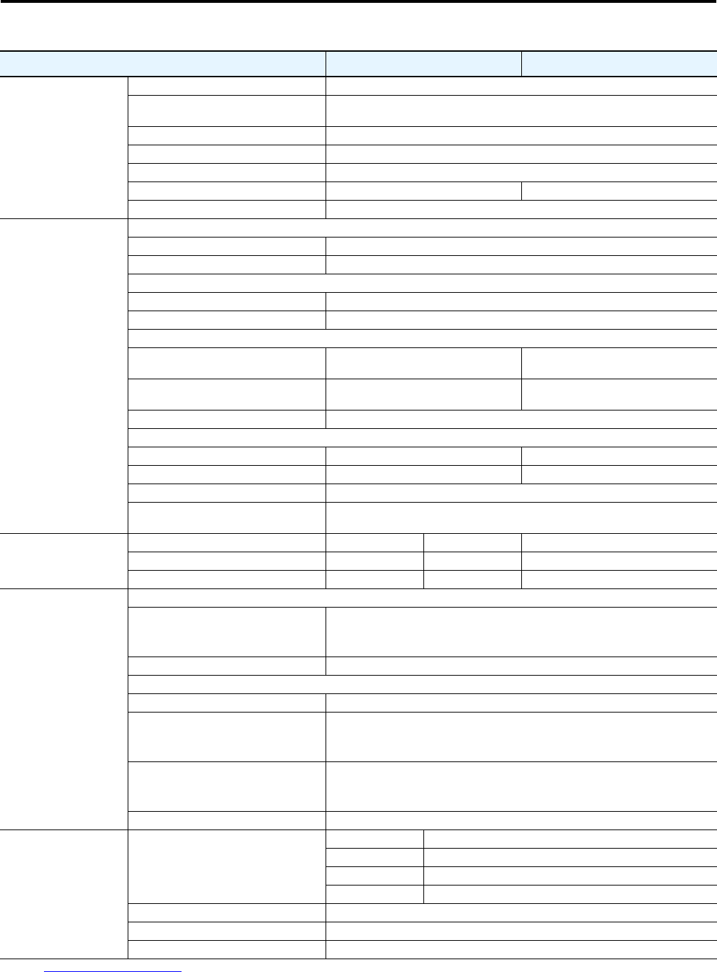
Other Rating
EMC Emission Levels
Conducted Radio Frequency Emissions
10V rms Communications Cables
10V rms (PE)
150 kHz…80 MHz
Radiated Emissions Class A
EMC Immunity Levels
Electrostatic Discharge 4 kV contact and 8 kV Air
Radio Frequency Electromagnetic Field
10V/m, 80 MHz…1 GHz
3V/m, 1.4 GHz…2 GHz
1V/m, 2.0 GHz …2.7 GHz
Fast Transient
2 kV (Power)
2 kV (PE)
1 kV (Communications and Control)
Surge Transient 1 kV (12) L-L, 2 kV (2) L-N (Earth)
Other Rating
Overload Current Range
280_-____-10A-* 0.24…1.2 A
280_-____-10B-* 0.5…2.5 A
280_-____-10C-* 1.1…5.5 A
280_-____-25D-* 3.2…16 A
Trip Classes ➊ 10, 15, 20
Trip Rating 120% of Full Load current (FLC) Setting
Number of poles 3
➊Refer to Motor Overload Trip Curves on page 243