
User Manual Owner's manual
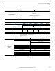
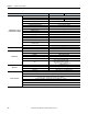

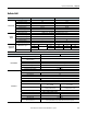
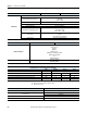
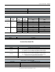
Table Of Contents
- ArmorStart Distributed Motor Controller with EtherNet/IP User Manual
- European Communities (EC) Directive Compliance
- Table of Contents
- Chapter 1
- Product Overview
- Introduction
- Description
- Catalog Number Explanation
- Operation
- Mode of Operation
- Description of Features
- Embedded Switch Technology
- Switched vs. Unswitched Control Power Input/Output (I/O) Connections
- EtherNet/IP™ Ports
- Embedded Web Server
- EtherNet/IP LED Status Indication
- Control Module LED Status and Reset
- Electronic Data Sheet (EDS)
- Fault Diagnostics
- Standard Features
- Factory-Installed Options
- Optional HOA Keypad Configuration (Bulletin 280E/281E only)
- Optional HOA Selector Keypad with Jog Function (Bulletin 284E only)
- Source Brake Contactor and Connector (Bulletin 284E only)
- EMI Filter (Bulletin 284E only)
- Dynamic Brake Connector (Bulletin 284E only)
- IP67 Dynamic Brake Resistor (Bulletin 284E only)
- Output Contactor (Bulletin 284E only)
- Shielded Motor Cable (Bulletin 284E only)
- ArmorStart® EtherNet/ IP Features
- Notes:
- Product Overview
- Chapter 2
- Installation and Wiring
- Receiving
- Unpacking
- Inspecting
- Storing
- General Precautions
- Precautions for Bulletin 280E/281E Applications
- Precautions for Bulletin 284E Applications
- Dimensions
- Mount Orientation
- Operation
- Wiring
- Terminal Designations
- Control Power Wiring
- ArmorStart with EtherNet/IP Internal Wiring
- AC Supply Considerations for Bulletin 284E Units
- Electromagnetic Compatibility (EMC)
- Grounding
- ArmorConnect Power Media
- ArmorConnect Connections
- ArmorConnect Cable Ratings
- Ethernet and I/O Connections
- Power Connections
- Optional Locking Clip
- Installation and Wiring
- Chapter 3
- Chapter 4
- Chapter 5
- Chapter 6
- Chapter 7
- Bulletin 280E/281E/284E Programmable Parameters
- Basic Setup Parameters
- Parameter Groups
- ArmorStart EtherNet/IP Parameters
- Bulletin 280E/281E
- Bulletin 284E
- Basic Status Group
- Produced Assembly Config Group
- Starter Protection Group
- User I/O Configuration Group
- Miscellaneous Configuration Group
- Drive I/O Configuration Group (Bulletin 284E only)
- Drive Display Group (Bulletin 284E only)
- Drive Setup Group (Bulletin 284E only)
- Drive Advanced Setup Group (Bulletin 284E only)
- Clear a Type 1 Fault and Restart the Drive
- Clear an Overvoltage, Undervoltage, or Heatsink OvrTmp Fault without Restarting the Drive
- How StepLogic Works
- StepLogic Settings
- Linear List of Parameters for Bulletin 280E/281E and Bulletin 284E
- Bulletin 280E/281E/284E Programmable Parameters
- Chapter 8
- Chapter 9
- Chapter 10
- Chapter 11
- Chapter 12
- Appendix A
- Applying More Than One ArmorStart Motor Controller in a Single Branch Circuit on Industrial Machinery
- Introduction
- ArmorStart LT Product Family
- Multiple-Motor Branch Circuits and Motor Controllers Listed for Group Installation – General
- Maximum Fuse Ampere Rating According to 7.2.10.4(1) and 7.2.10.4(2)
- Explanatory Example
- Input and Output Conductors of Bulletin 290E and 291E Controllers (a)
- Input and Output Conductors of Bulletin 294E Controllers (b)
- Combined Load Conductors (c)
- Applying More Than One ArmorStart Motor Controller in a Single Branch Circuit on Industrial Machinery
- Appendix B
- CIP Information
- High Level Product Description
- CIP Explicit Connection Behavior
- CIP Object Requirements
- Identity Object
- Assembly Object
- Connection Manager Object
- Discrete Input Point Object
- Discrete Output Point Object
- Parameter Object
- Parameter Group Object
- Discrete Input Group Object
- Discrete Output Group Object
- Control Supervisor Object
- Overload Object
- Device Level Ring (DLR) Object
- Qos Object
- DPI Fault Object
- DPI Alarm Object
- Interface Object
- TCP/IP Interface Object
- Ethernet Link Object
- CIP Information
- Appendix C
- Using DeviceLogix
- DeviceLogix Programming
- DeviceLogix Programming Example
- Import and Export
- Bulletin 284 - VFD Preset Speed Example
- DeviceLogix Ladder Editor Example
- ArmorStart 280 and 281 Status Bits
- Bulletin 280 and 281 ArmorStart Fault Bits
- Bulletin 280 and 281 ArmorStart Outputs
- Bulletin 280 and 281 ArmorStart Produced Network Bits
- Bulletin 284 ArmorStart Status Bits
- Bulletin 284 ArmorStart Fault Bits
- Bulletin 284 ArmorStart Outputs
- Bulletin 284 ArmorStart Produced Network Bits
- Using DeviceLogix
- Appendix D
- Appendix E
- Appendix F
- Back Cover

242 Rockwell Automation Publication 280E-UM001B-EN-P - July 2012
Chapter 11 Specifications for EtherNet/IP
Output Ratings – Sourced
from Control Circuit (A1/A2)
Rated Operation Voltage 26.4V DC
Rate Insulation Voltage 250V
Dielectric Withstand 1500V AC (UL) 2000V AC (IEC)
Operating Frequency Solid state sourcing output
Type of Current 24V DC
Conventional Thermal Current Ith 0.5 A each, 1 A max. combined
Peak Output Current Current limited 2-8 amps (5 amps nominal) @ 24V DC
Type of Contacts Normally open (N.O.)
Number of Contacts 2
Load Types Resistive or light inductive
Surge Suppression Integrated diode, clamps @ 35V DC
Thermo-Protection Integrated short circuit and over current protection
Maximum Cycle Rate 30 operations/minute capacitive and inductive loads
Maximum Blocking Voltage 35V DC
Maximum On-State Voltage @
Maximum Output
1.5V DC
Maximum Off-State Leakage Current 10 μA
Device Level Ring (DLR)
Beacon-based performance including IEEE 1588 end to end transparent clock
Fault Recovery Ring recovery time is less than 3 ms for a 50 node network
Ethernet Port
EtherNet Receptacles 2 D-coded, 4-pin female M12 connectors
Ports Embedded switch with 2 ports
IP Address DHCP enabled by default
DHCP Timeout 30 s
Communication Rate 10/100 Mbs with auto negotiate half duplex and full duplex
Data
• Transported over both TCP and UDP
• Min. of 500 I/O packets/second (pps)
• Supports up to 150 concurrent TCP sockets
Web Server
Embedded web server
Security Login and password configurable
E-mail Support Simple Mail Transfer Protocol (SMTP)
Configuration Status, diagnostics, and configuration tabs
Device Connections
Supports scheduled (Class 1) and unscheduled (Class 3 & UCMM) connections
6 - Class 3 connections are supported simultaneously
Supports up to 2 Class 1 CIP connections [Exclusive owner (data) or listen-only]. One connection per PLC.
Listen only connection requires a data connection to be established.
Class 1 Connection API: 2…3200 ms, Class 3 Connection API: 100…10 000 ms
20 ms default (2 ms minimum)
3 concurrent Encapsulation sessions
TCP port supports 5 concurrent incoming connections
UL/NEMA IEC