
User Manual Owner's manual
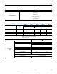
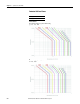
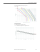
Table Of Contents
- ArmorStart Distributed Motor Controller with EtherNet/IP User Manual
- European Communities (EC) Directive Compliance
- Table of Contents
- Chapter 1
- Product Overview
- Introduction
- Description
- Catalog Number Explanation
- Operation
- Mode of Operation
- Description of Features
- Embedded Switch Technology
- Switched vs. Unswitched Control Power Input/Output (I/O) Connections
- EtherNet/IP™ Ports
- Embedded Web Server
- EtherNet/IP LED Status Indication
- Control Module LED Status and Reset
- Electronic Data Sheet (EDS)
- Fault Diagnostics
- Standard Features
- Factory-Installed Options
- Optional HOA Keypad Configuration (Bulletin 280E/281E only)
- Optional HOA Selector Keypad with Jog Function (Bulletin 284E only)
- Source Brake Contactor and Connector (Bulletin 284E only)
- EMI Filter (Bulletin 284E only)
- Dynamic Brake Connector (Bulletin 284E only)
- IP67 Dynamic Brake Resistor (Bulletin 284E only)
- Output Contactor (Bulletin 284E only)
- Shielded Motor Cable (Bulletin 284E only)
- ArmorStart® EtherNet/ IP Features
- Notes:
- Product Overview
- Chapter 2
- Installation and Wiring
- Receiving
- Unpacking
- Inspecting
- Storing
- General Precautions
- Precautions for Bulletin 280E/281E Applications
- Precautions for Bulletin 284E Applications
- Dimensions
- Mount Orientation
- Operation
- Wiring
- Terminal Designations
- Control Power Wiring
- ArmorStart with EtherNet/IP Internal Wiring
- AC Supply Considerations for Bulletin 284E Units
- Electromagnetic Compatibility (EMC)
- Grounding
- ArmorConnect Power Media
- ArmorConnect Connections
- ArmorConnect Cable Ratings
- Ethernet and I/O Connections
- Power Connections
- Optional Locking Clip
- Installation and Wiring
- Chapter 3
- Chapter 4
- Chapter 5
- Chapter 6
- Chapter 7
- Bulletin 280E/281E/284E Programmable Parameters
- Basic Setup Parameters
- Parameter Groups
- ArmorStart EtherNet/IP Parameters
- Bulletin 280E/281E
- Bulletin 284E
- Basic Status Group
- Produced Assembly Config Group
- Starter Protection Group
- User I/O Configuration Group
- Miscellaneous Configuration Group
- Drive I/O Configuration Group (Bulletin 284E only)
- Drive Display Group (Bulletin 284E only)
- Drive Setup Group (Bulletin 284E only)
- Drive Advanced Setup Group (Bulletin 284E only)
- Clear a Type 1 Fault and Restart the Drive
- Clear an Overvoltage, Undervoltage, or Heatsink OvrTmp Fault without Restarting the Drive
- How StepLogic Works
- StepLogic Settings
- Linear List of Parameters for Bulletin 280E/281E and Bulletin 284E
- Bulletin 280E/281E/284E Programmable Parameters
- Chapter 8
- Chapter 9
- Chapter 10
- Chapter 11
- Chapter 12
- Appendix A
- Applying More Than One ArmorStart Motor Controller in a Single Branch Circuit on Industrial Machinery
- Introduction
- ArmorStart LT Product Family
- Multiple-Motor Branch Circuits and Motor Controllers Listed for Group Installation – General
- Maximum Fuse Ampere Rating According to 7.2.10.4(1) and 7.2.10.4(2)
- Explanatory Example
- Input and Output Conductors of Bulletin 290E and 291E Controllers (a)
- Input and Output Conductors of Bulletin 294E Controllers (b)
- Combined Load Conductors (c)
- Applying More Than One ArmorStart Motor Controller in a Single Branch Circuit on Industrial Machinery
- Appendix B
- CIP Information
- High Level Product Description
- CIP Explicit Connection Behavior
- CIP Object Requirements
- Identity Object
- Assembly Object
- Connection Manager Object
- Discrete Input Point Object
- Discrete Output Point Object
- Parameter Object
- Parameter Group Object
- Discrete Input Group Object
- Discrete Output Group Object
- Control Supervisor Object
- Overload Object
- Device Level Ring (DLR) Object
- Qos Object
- DPI Fault Object
- DPI Alarm Object
- Interface Object
- TCP/IP Interface Object
- Ethernet Link Object
- CIP Information
- Appendix C
- Using DeviceLogix
- DeviceLogix Programming
- DeviceLogix Programming Example
- Import and Export
- Bulletin 284 - VFD Preset Speed Example
- DeviceLogix Ladder Editor Example
- ArmorStart 280 and 281 Status Bits
- Bulletin 280 and 281 ArmorStart Fault Bits
- Bulletin 280 and 281 ArmorStart Outputs
- Bulletin 280 and 281 ArmorStart Produced Network Bits
- Bulletin 284 ArmorStart Status Bits
- Bulletin 284 ArmorStart Fault Bits
- Bulletin 284 ArmorStart Outputs
- Bulletin 284 ArmorStart Produced Network Bits
- Using DeviceLogix
- Appendix D
- Appendix E
- Appendix F
- Back Cover
Rockwell Automation Publication 280E-UM001B-EN-P - July 2012 249
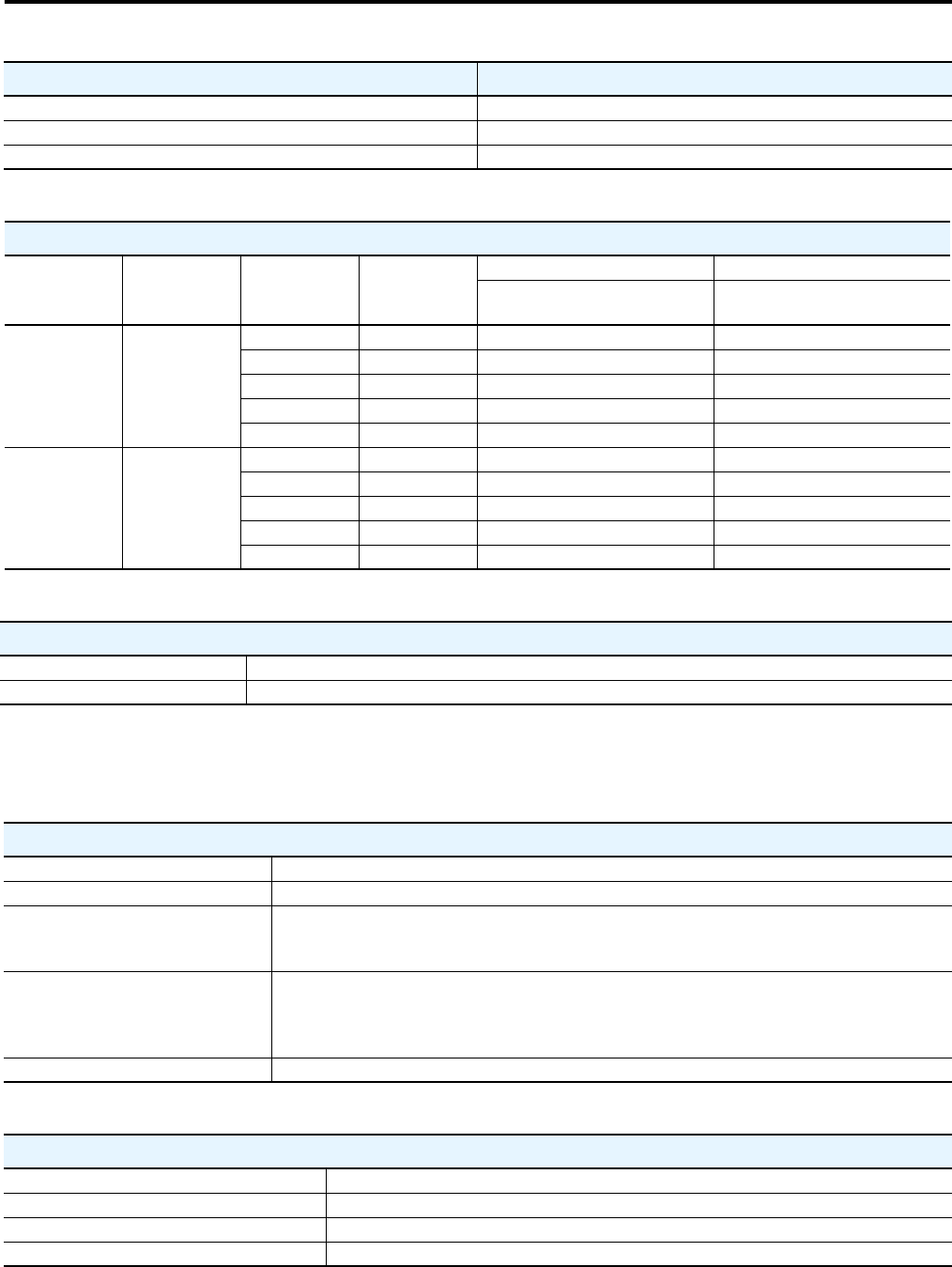
Specifications for EtherNet/IP Chapter 11
Sensorless Vector Control (SVC)
Skip Frequency ✓
StepLogic Functionality ✓
Timer/Counter Functions ✓
Drive Characteristics Sensorless Vector Control
Drive Ratings – VFD Output Current vs. Input Current
Line Voltage [V]
Frequency
[Hz]
3-Phase kW
Rating
3-Phase Hp
Rating
Output Current [A] Input Current [A]
Sensorless Vector
Control
Sensorless Vector
Control
380 50
0.4 — 1.4 2.15
0.75 — 2.3 3.80
1.5 — 4.0 6.40
2.2 — 6.0 9.00
3.0 — 7.6 12.40
460 60
— 0.5 1.4 1.85
—1 2.3 3.45
—2 4.0 5.57
—3 6.0 8.20
— 5 7.6 12.5
PowerFlex 40
Output Frequency 0…400 Hz (Programmable)
Efficiency 97.5% (Typical)
Protective Specifications – Sensorless Vector Control
Motor Protection I
2
t overload protection – 150% for 60 seconds, 200% for 3 seconds (provides Class 10 protection)
Overcurrent 200% hardware limit, 300% instantaneous fault
Over Voltage
200…240V AC Input – Trip occurs @ 405V DC bus voltage (equivalent to 290V AC incoming line)
380…460V AC Input – Trip occurs @ 810V DC bus voltage (equivalent to 575V AC incoming line)
460…600V AC Input – Trip occurs @ 1005V DC bus voltage (equivalent to 711V AC incoming line)
Under Voltage
200…240V AC Input – Trip occurs @ 210V DC bus voltage (equivalent to 150V AC incoming line)
380…480V AC Input – Trip occurs @ 390V DC bus voltage (equivalent to 275V AC incoming line)
460…600V AC Input – If 600V rated trip occurs @ 487V DC bus voltage (344V AC incoming line);
If 480V rated trip occurs @ 390V DC bus voltage (275V AC incoming line)
Faultless Power Ride Through 100 milliseconds
Control Specifications – Sensorless Vector Control
Carrier Frequency 2…16 kHz. Drive rating based on 4 kHz.
Frequency Accuracy – Digital Input Within ±0.05% of set output frequency.
Speed Regulation – Open Loop with Slip Compensation ±1% of base speed across a 60:1 speed range
Stop Modes Multiple programmable stop modes including – Ramp, Coast, DC-Brake, Ramp-to-Hold and S Curve.