
User Manual Owner's manual
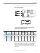
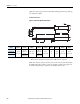
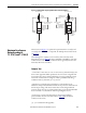
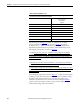
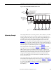
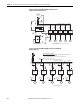
Table Of Contents
- ArmorStart Distributed Motor Controller with EtherNet/IP User Manual
- European Communities (EC) Directive Compliance
- Table of Contents
- Chapter 1
- Product Overview
- Introduction
- Description
- Catalog Number Explanation
- Operation
- Mode of Operation
- Description of Features
- Embedded Switch Technology
- Switched vs. Unswitched Control Power Input/Output (I/O) Connections
- EtherNet/IP™ Ports
- Embedded Web Server
- EtherNet/IP LED Status Indication
- Control Module LED Status and Reset
- Electronic Data Sheet (EDS)
- Fault Diagnostics
- Standard Features
- Factory-Installed Options
- Optional HOA Keypad Configuration (Bulletin 280E/281E only)
- Optional HOA Selector Keypad with Jog Function (Bulletin 284E only)
- Source Brake Contactor and Connector (Bulletin 284E only)
- EMI Filter (Bulletin 284E only)
- Dynamic Brake Connector (Bulletin 284E only)
- IP67 Dynamic Brake Resistor (Bulletin 284E only)
- Output Contactor (Bulletin 284E only)
- Shielded Motor Cable (Bulletin 284E only)
- ArmorStart® EtherNet/ IP Features
- Notes:
- Product Overview
- Chapter 2
- Installation and Wiring
- Receiving
- Unpacking
- Inspecting
- Storing
- General Precautions
- Precautions for Bulletin 280E/281E Applications
- Precautions for Bulletin 284E Applications
- Dimensions
- Mount Orientation
- Operation
- Wiring
- Terminal Designations
- Control Power Wiring
- ArmorStart with EtherNet/IP Internal Wiring
- AC Supply Considerations for Bulletin 284E Units
- Electromagnetic Compatibility (EMC)
- Grounding
- ArmorConnect Power Media
- ArmorConnect Connections
- ArmorConnect Cable Ratings
- Ethernet and I/O Connections
- Power Connections
- Optional Locking Clip
- Installation and Wiring
- Chapter 3
- Chapter 4
- Chapter 5
- Chapter 6
- Chapter 7
- Bulletin 280E/281E/284E Programmable Parameters
- Basic Setup Parameters
- Parameter Groups
- ArmorStart EtherNet/IP Parameters
- Bulletin 280E/281E
- Bulletin 284E
- Basic Status Group
- Produced Assembly Config Group
- Starter Protection Group
- User I/O Configuration Group
- Miscellaneous Configuration Group
- Drive I/O Configuration Group (Bulletin 284E only)
- Drive Display Group (Bulletin 284E only)
- Drive Setup Group (Bulletin 284E only)
- Drive Advanced Setup Group (Bulletin 284E only)
- Clear a Type 1 Fault and Restart the Drive
- Clear an Overvoltage, Undervoltage, or Heatsink OvrTmp Fault without Restarting the Drive
- How StepLogic Works
- StepLogic Settings
- Linear List of Parameters for Bulletin 280E/281E and Bulletin 284E
- Bulletin 280E/281E/284E Programmable Parameters
- Chapter 8
- Chapter 9
- Chapter 10
- Chapter 11
- Chapter 12
- Appendix A
- Applying More Than One ArmorStart Motor Controller in a Single Branch Circuit on Industrial Machinery
- Introduction
- ArmorStart LT Product Family
- Multiple-Motor Branch Circuits and Motor Controllers Listed for Group Installation – General
- Maximum Fuse Ampere Rating According to 7.2.10.4(1) and 7.2.10.4(2)
- Explanatory Example
- Input and Output Conductors of Bulletin 290E and 291E Controllers (a)
- Input and Output Conductors of Bulletin 294E Controllers (b)
- Combined Load Conductors (c)
- Applying More Than One ArmorStart Motor Controller in a Single Branch Circuit on Industrial Machinery
- Appendix B
- CIP Information
- High Level Product Description
- CIP Explicit Connection Behavior
- CIP Object Requirements
- Identity Object
- Assembly Object
- Connection Manager Object
- Discrete Input Point Object
- Discrete Output Point Object
- Parameter Object
- Parameter Group Object
- Discrete Input Group Object
- Discrete Output Group Object
- Control Supervisor Object
- Overload Object
- Device Level Ring (DLR) Object
- Qos Object
- DPI Fault Object
- DPI Alarm Object
- Interface Object
- TCP/IP Interface Object
- Ethernet Link Object
- CIP Information
- Appendix C
- Using DeviceLogix
- DeviceLogix Programming
- DeviceLogix Programming Example
- Import and Export
- Bulletin 284 - VFD Preset Speed Example
- DeviceLogix Ladder Editor Example
- ArmorStart 280 and 281 Status Bits
- Bulletin 280 and 281 ArmorStart Fault Bits
- Bulletin 280 and 281 ArmorStart Outputs
- Bulletin 280 and 281 ArmorStart Produced Network Bits
- Bulletin 284 ArmorStart Status Bits
- Bulletin 284 ArmorStart Fault Bits
- Bulletin 284 ArmorStart Outputs
- Bulletin 284 ArmorStart Produced Network Bits
- Using DeviceLogix
- Appendix D
- Appendix E
- Appendix F
- Back Cover
270 Rockwell Automation Publication 280E-UM001B-EN-P - July 2012
Appendix A Applying More Than One ArmorStart Motor Controller in a Single Branch Circuit on Industrial Machinery
Figure 98 - ArmorStart LT NFPA 79 Multi-Motor Branch Circuit —
Conductor and Controller Protection
Figure 99 - ArmorStart LT NFPA 79 Multi-Motor Branch Circuit Minimum
Conductor Ampacity
½ HP
Bulletin 294
2 HP
Bulletin 294
5 HP
Bulletin 291
5 HP
Bulletin 290
1 HP
Bulletin 294
Overload
Class 10
Overload
Class 10
Overload
Class 10/15/20
Overload
Class 10/15/20
Overload
Class 10
Nameplate* Nameplate* Nameplate* Nameplate* Nameplate*
1/2 HP
FLC =
1.1 A**
2 HP
FLC =
3.4 A**
5 HP
FLC =
7.6 A**
5 HP
FLC =
7.6 A**
1 HP
FLC =
2.1 A**
14 AWG14 AWG
14 AWG14 AWG
14 AWG14 AWG
14 AWG14 AWG
14 AWG14 AWG
Combined Load Conductors
10 AWG
* Each controller is suitable for group installation with the same maximum ratings of fuse.
** Table 430.250 of NFPA 70-2011
Electrical Supply -
480Y/277V
Available Fault Current
Sym. Amps RMS 9 KA
Disconnecting
Means
Branch short-circuit
and ground-fault
protection device
Fuses
45 A Max,
CC, J or T
Controller
ratings
further
restrict the
fuse
Compare to
controller max
fuse ratings
“Suitable for Motor Group Installation”
Max. Ratings
5 KA 10 KA
45A 45A*
Sym. Amps RMS
Fuse
* Type CC, J and T fuses only
Conductor
protection -
60 A max,
any class
Determine
fuse class
and max
rating for
conductor
protection
Conductor
protection
“Smallest
conductor”
7.2.10.4(2) -
“smallest
conductor in
the circuit”
= 14 AWG
Table 7.2.10.4
Max
Fuse
AWG (A)
- -
14 60
12 80
10 100
8 150
- -
a
d
d
a
b
c
Electrical Supply
Min Amp. =
125% * 1.8 A
Min Amp. =
125% * 5.5 A
Min Amp. =
125% * 7.6 A
Min Amp. =
125% * 7.6 A
Min Amp. =
125% * 3.0 A
Min Amp. =
125% * 1.1A
Min Amp. =
125% * 3.4 A
Min Amp. =
125% * 7.6 A
Min Amp. =
125% * 7.6 A
Min Amp. =
125% * 2.1 A
Minimum Required Ampacity (MRA)
MRA = 1.25 * Max {controller input currents} + Sum {remaining controller input currents}
Controller input currents = {I1,I2,I3,I4,I5}
Max controller input current = I3 = I4, choose I3 as Max (either is ok)
MRA = 1.25 * I3 + (I1 + I2 + I4 + I5}
= 1.25 * 7.6 A + (1.8 A + 5.5 A + 7.6 A + 3.0 A) = 27.4 A
c
a
b
a
b
½ HP
Bulletin
294
2 HP
Bulletin
294
5 HP
Bulletin
291
5 HP
Bulletin
290
1 HP
Bulletin
294
Combined Load Conductors
I1 =
1.8 A
I2 =
5.5 A
I3 =
7.6 A
I4 =
7.6 A
I5 =
3.0 A
1/2 HP
FLC =
1.1 A**
2 HP
FLC =
3.4 A**
5 HP
FLC =
7.6 A**
5 HP
FLC =
7.6 A**
1 HP
FLC =
2.1 A**
** Table 430.250 of NFPA 70-2011
1.1 A 3.4 A 7.6 A 7.6 A 2.1 A
14 AWG14 AWG
14 AWG14 AWG
14 AWG14 AWG
14 AWG14 AWG
14 AWG14 AWG
10 AWG