
User Manual Owner's manual
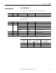
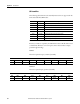
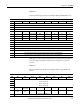
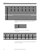
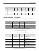
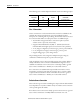
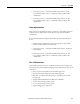
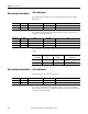
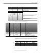
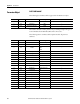
Table Of Contents
- ArmorStart Distributed Motor Controller with EtherNet/IP User Manual
- European Communities (EC) Directive Compliance
- Table of Contents
- Chapter 1
- Product Overview
- Introduction
- Description
- Catalog Number Explanation
- Operation
- Mode of Operation
- Description of Features
- Embedded Switch Technology
- Switched vs. Unswitched Control Power Input/Output (I/O) Connections
- EtherNet/IP™ Ports
- Embedded Web Server
- EtherNet/IP LED Status Indication
- Control Module LED Status and Reset
- Electronic Data Sheet (EDS)
- Fault Diagnostics
- Standard Features
- Factory-Installed Options
- Optional HOA Keypad Configuration (Bulletin 280E/281E only)
- Optional HOA Selector Keypad with Jog Function (Bulletin 284E only)
- Source Brake Contactor and Connector (Bulletin 284E only)
- EMI Filter (Bulletin 284E only)
- Dynamic Brake Connector (Bulletin 284E only)
- IP67 Dynamic Brake Resistor (Bulletin 284E only)
- Output Contactor (Bulletin 284E only)
- Shielded Motor Cable (Bulletin 284E only)
- ArmorStart® EtherNet/ IP Features
- Notes:
- Product Overview
- Chapter 2
- Installation and Wiring
- Receiving
- Unpacking
- Inspecting
- Storing
- General Precautions
- Precautions for Bulletin 280E/281E Applications
- Precautions for Bulletin 284E Applications
- Dimensions
- Mount Orientation
- Operation
- Wiring
- Terminal Designations
- Control Power Wiring
- ArmorStart with EtherNet/IP Internal Wiring
- AC Supply Considerations for Bulletin 284E Units
- Electromagnetic Compatibility (EMC)
- Grounding
- ArmorConnect Power Media
- ArmorConnect Connections
- ArmorConnect Cable Ratings
- Ethernet and I/O Connections
- Power Connections
- Optional Locking Clip
- Installation and Wiring
- Chapter 3
- Chapter 4
- Chapter 5
- Chapter 6
- Chapter 7
- Bulletin 280E/281E/284E Programmable Parameters
- Basic Setup Parameters
- Parameter Groups
- ArmorStart EtherNet/IP Parameters
- Bulletin 280E/281E
- Bulletin 284E
- Basic Status Group
- Produced Assembly Config Group
- Starter Protection Group
- User I/O Configuration Group
- Miscellaneous Configuration Group
- Drive I/O Configuration Group (Bulletin 284E only)
- Drive Display Group (Bulletin 284E only)
- Drive Setup Group (Bulletin 284E only)
- Drive Advanced Setup Group (Bulletin 284E only)
- Clear a Type 1 Fault and Restart the Drive
- Clear an Overvoltage, Undervoltage, or Heatsink OvrTmp Fault without Restarting the Drive
- How StepLogic Works
- StepLogic Settings
- Linear List of Parameters for Bulletin 280E/281E and Bulletin 284E
- Bulletin 280E/281E/284E Programmable Parameters
- Chapter 8
- Chapter 9
- Chapter 10
- Chapter 11
- Chapter 12
- Appendix A
- Applying More Than One ArmorStart Motor Controller in a Single Branch Circuit on Industrial Machinery
- Introduction
- ArmorStart LT Product Family
- Multiple-Motor Branch Circuits and Motor Controllers Listed for Group Installation – General
- Maximum Fuse Ampere Rating According to 7.2.10.4(1) and 7.2.10.4(2)
- Explanatory Example
- Input and Output Conductors of Bulletin 290E and 291E Controllers (a)
- Input and Output Conductors of Bulletin 294E Controllers (b)
- Combined Load Conductors (c)
- Applying More Than One ArmorStart Motor Controller in a Single Branch Circuit on Industrial Machinery
- Appendix B
- CIP Information
- High Level Product Description
- CIP Explicit Connection Behavior
- CIP Object Requirements
- Identity Object
- Assembly Object
- Connection Manager Object
- Discrete Input Point Object
- Discrete Output Point Object
- Parameter Object
- Parameter Group Object
- Discrete Input Group Object
- Discrete Output Group Object
- Control Supervisor Object
- Overload Object
- Device Level Ring (DLR) Object
- Qos Object
- DPI Fault Object
- DPI Alarm Object
- Interface Object
- TCP/IP Interface Object
- Ethernet Link Object
- CIP Information
- Appendix C
- Using DeviceLogix
- DeviceLogix Programming
- DeviceLogix Programming Example
- Import and Export
- Bulletin 284 - VFD Preset Speed Example
- DeviceLogix Ladder Editor Example
- ArmorStart 280 and 281 Status Bits
- Bulletin 280 and 281 ArmorStart Fault Bits
- Bulletin 280 and 281 ArmorStart Outputs
- Bulletin 280 and 281 ArmorStart Produced Network Bits
- Bulletin 284 ArmorStart Status Bits
- Bulletin 284 ArmorStart Fault Bits
- Bulletin 284 ArmorStart Outputs
- Bulletin 284 ArmorStart Produced Network Bits
- Using DeviceLogix
- Appendix D
- Appendix E
- Appendix F
- Back Cover

284 Rockwell Automation Publication 280E-UM001B-EN-P – July 2012
Appendix B CIP Information
Note: Byte 0 - 3 refers to PLC communication status. All 1s (bit high) indicates a
connection fault (communication fault) exists or all 0s (bit low) connection
is normal.
Instance 162
This is the standard output (consumed) assembly with
Network Inputs.
Instance 166
This is the standard output (consumed) assembly for Inverter Type Distributed
Starters with network inputs.
7 OutputFrequency (High) (xxx.x Hz)
8 Pt07DeviceOut Pt06DeviceOut Pt05DeviceOut Pt04DeviceOut Pt03DeviceOut Pt02DeviceOut Pt01DeviceOut Pt00DeviceOut
9 LogicEnable Pt14DeviceOut Pt14DeviceOut Pt13DeviceOut Pt11DeviceOut P10DeviceOut Pt09DeviceOut Pt08DeviceOut
10 Value of the parameter pointed to by “Parameter 13 Prod Assy Word 0" (low byte)” - Int00DeviceOut
11 Value of the parameter pointed to by “Parameter 13 Prod Assy Word 0" (high byte)” - Int00DeviceOut
12 Value of the parameter pointed to by “Parameter 14 Prod Assy Word 1" (low byte)” - Int01DeviceOut
13 Value of the parameter pointed to by “Parameter 14 Prod Assy Word 1" (high byte)” - Int01DeviceOut
14 Value of the parameter pointed to by “Parameter 15 Prod Assy Word 2" (low byte)” - Int02DeviceOut
15 Value of the parameter pointed to by “Parameter 15 Prod Assy Word 2" (high byte)” - Int02DeviceOut
16 Value of the parameter pointed to by “Parameter 16 Prod Assy Word 3" (low byte)” - Int03DeviceOut
17 Value of the parameter pointed to by “Parameter 16 Prod Assy Word 3" (high byte)” - Int03DeviceOut
Produce Assembly - Instance 151 “Drive Status” - 284E Starters
Byte Bit 7 Bit 6 Bit 5 Bit 4 Bit 3 Bit 2 Bit 1 Bit 0
** Contactor Reference
Contactor 1 Source Brake Contactor status
Contactor 2 Output Contactor status
Instance 162 Default Consumed DOL and Reversing Starter
ByteBit 7Bit 6Bit 5Bit 4Bit 3Bit 2Bit 1Bit 0
0 OutB OutA — — — ResetFault RunReverse RunForward
1 Pt07DeviceIn Pt06DeviceIn Pt05DeviceIn Pt04DeviceIn Pt03DeviceIn Pt02DeviceIn Pt01DeviceIn Pt00DeviceIn
2 Pt15DeviceIn Pt14DeviceIn Pt13DeviceIn Pt12DeviceIn Pt11DeviceIn Pt10DeviceIn Pt09DeviceIn Pt08DeviceIn