
User Manual Owner's manual
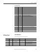
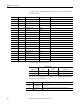
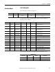
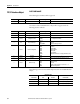
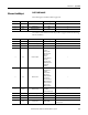
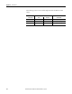
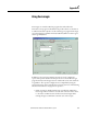
Table Of Contents
- ArmorStart Distributed Motor Controller with EtherNet/IP User Manual
- European Communities (EC) Directive Compliance
- Table of Contents
- Chapter 1
- Product Overview
- Introduction
- Description
- Catalog Number Explanation
- Operation
- Mode of Operation
- Description of Features
- Embedded Switch Technology
- Switched vs. Unswitched Control Power Input/Output (I/O) Connections
- EtherNet/IP™ Ports
- Embedded Web Server
- EtherNet/IP LED Status Indication
- Control Module LED Status and Reset
- Electronic Data Sheet (EDS)
- Fault Diagnostics
- Standard Features
- Factory-Installed Options
- Optional HOA Keypad Configuration (Bulletin 280E/281E only)
- Optional HOA Selector Keypad with Jog Function (Bulletin 284E only)
- Source Brake Contactor and Connector (Bulletin 284E only)
- EMI Filter (Bulletin 284E only)
- Dynamic Brake Connector (Bulletin 284E only)
- IP67 Dynamic Brake Resistor (Bulletin 284E only)
- Output Contactor (Bulletin 284E only)
- Shielded Motor Cable (Bulletin 284E only)
- ArmorStart® EtherNet/ IP Features
- Notes:
- Product Overview
- Chapter 2
- Installation and Wiring
- Receiving
- Unpacking
- Inspecting
- Storing
- General Precautions
- Precautions for Bulletin 280E/281E Applications
- Precautions for Bulletin 284E Applications
- Dimensions
- Mount Orientation
- Operation
- Wiring
- Terminal Designations
- Control Power Wiring
- ArmorStart with EtherNet/IP Internal Wiring
- AC Supply Considerations for Bulletin 284E Units
- Electromagnetic Compatibility (EMC)
- Grounding
- ArmorConnect Power Media
- ArmorConnect Connections
- ArmorConnect Cable Ratings
- Ethernet and I/O Connections
- Power Connections
- Optional Locking Clip
- Installation and Wiring
- Chapter 3
- Chapter 4
- Chapter 5
- Chapter 6
- Chapter 7
- Bulletin 280E/281E/284E Programmable Parameters
- Basic Setup Parameters
- Parameter Groups
- ArmorStart EtherNet/IP Parameters
- Bulletin 280E/281E
- Bulletin 284E
- Basic Status Group
- Produced Assembly Config Group
- Starter Protection Group
- User I/O Configuration Group
- Miscellaneous Configuration Group
- Drive I/O Configuration Group (Bulletin 284E only)
- Drive Display Group (Bulletin 284E only)
- Drive Setup Group (Bulletin 284E only)
- Drive Advanced Setup Group (Bulletin 284E only)
- Clear a Type 1 Fault and Restart the Drive
- Clear an Overvoltage, Undervoltage, or Heatsink OvrTmp Fault without Restarting the Drive
- How StepLogic Works
- StepLogic Settings
- Linear List of Parameters for Bulletin 280E/281E and Bulletin 284E
- Bulletin 280E/281E/284E Programmable Parameters
- Chapter 8
- Chapter 9
- Chapter 10
- Chapter 11
- Chapter 12
- Appendix A
- Applying More Than One ArmorStart Motor Controller in a Single Branch Circuit on Industrial Machinery
- Introduction
- ArmorStart LT Product Family
- Multiple-Motor Branch Circuits and Motor Controllers Listed for Group Installation – General
- Maximum Fuse Ampere Rating According to 7.2.10.4(1) and 7.2.10.4(2)
- Explanatory Example
- Input and Output Conductors of Bulletin 290E and 291E Controllers (a)
- Input and Output Conductors of Bulletin 294E Controllers (b)
- Combined Load Conductors (c)
- Applying More Than One ArmorStart Motor Controller in a Single Branch Circuit on Industrial Machinery
- Appendix B
- CIP Information
- High Level Product Description
- CIP Explicit Connection Behavior
- CIP Object Requirements
- Identity Object
- Assembly Object
- Connection Manager Object
- Discrete Input Point Object
- Discrete Output Point Object
- Parameter Object
- Parameter Group Object
- Discrete Input Group Object
- Discrete Output Group Object
- Control Supervisor Object
- Overload Object
- Device Level Ring (DLR) Object
- Qos Object
- DPI Fault Object
- DPI Alarm Object
- Interface Object
- TCP/IP Interface Object
- Ethernet Link Object
- CIP Information
- Appendix C
- Using DeviceLogix
- DeviceLogix Programming
- DeviceLogix Programming Example
- Import and Export
- Bulletin 284 - VFD Preset Speed Example
- DeviceLogix Ladder Editor Example
- ArmorStart 280 and 281 Status Bits
- Bulletin 280 and 281 ArmorStart Fault Bits
- Bulletin 280 and 281 ArmorStart Outputs
- Bulletin 280 and 281 ArmorStart Produced Network Bits
- Bulletin 284 ArmorStart Status Bits
- Bulletin 284 ArmorStart Fault Bits
- Bulletin 284 ArmorStart Outputs
- Bulletin 284 ArmorStart Produced Network Bits
- Using DeviceLogix
- Appendix D
- Appendix E
- Appendix F
- Back Cover

Rockwell Automation Publication 280E-UM001B-EN-P – July 2012 301
CIP Information Appendix B
➊ The Fault text for this error is not return by the device, and is only reported as “Fault 45”.
DPI Alarm Object
CLASS CODE 0x0098
The following class attributes will be supported:
24 Power Loss Drive DC Bus Voltage remained below 85% of nominal bus voltage.
25 Under Voltage DC Bus Voltage fell below the minimum value.
26 Over Voltage DC Bus Voltage exceeded the maximum value.
27 MCB EEPROM This is a major fault which renders the ArmorStart inoperable.
28 Base EEPROM This is a major fault which renders the ArmorStart inoperable.
29 Drive EEPROM The drive EEPROM checksum checks have failed.
30 Wrong Base The ArmorStart controller is connected to the wrong base type.
31 Fan RMP The internal cooling fan is not running properly.
32 Power Unit A major failure has been detected in the drive power section.
33 Drive I/O Brd A failure has been detected in the drive control and I/O section.
34 Restart Retries Automatic fault reset and run retries exceeded.
35 Drive Aux In Flt The drive auxiliary input interlock is open inside the ArmorStart.
36 Analog Input (PF Fault Code 29)
37 Drv Param Reset Internal Drive Parameters (Parameters > 100) have been defaulted.
38 SCV Autotune The drive automatic tuning function was either aborted or failed.
39 Source Brake The source brake fuse has blown. Remove power and replace fuse.
40 Unknown Fault —
41 DB1 Comm Communication with an internal DB1 board has been lost.
42 DB1 Fault A fault has been detected with the operation of the Dynamic Brake.
43 DB Switch Short The Dynamic Brake switch is shorted.
44 Fault 44 —
45
➊
Incompatible COMM
Device
The Software revision of the Drive is not compatible with the ArmorStart.
Table 50 Bulletin 284E
Fault Code Fault Text Help Text
Attribute ID Access Rule Name Data Type Value
1 Get Class Revision UINT 1
2 Get Number of Instances UINT 1
3 Set Alarm Cmd Write USINT 0=NOP, 1=Clear Fault, 2=Clear Flt Queue
74 Get Alarm Instance Read UINT
The instance of the Fault Queue Entry containing information
about the Fault that tripped the Device.
6 Get Number of Recorded Faults UINT The number of Faults recorded in the Fault Queue.