
User Manual Owner's manual
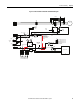
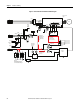
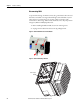
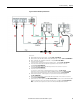
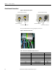
Table Of Contents
- ArmorStart Distributed Motor Controller with EtherNet/IP User Manual
- European Communities (EC) Directive Compliance
- Table of Contents
- Chapter 1
- Product Overview
- Introduction
- Description
- Catalog Number Explanation
- Operation
- Mode of Operation
- Description of Features
- Embedded Switch Technology
- Switched vs. Unswitched Control Power Input/Output (I/O) Connections
- EtherNet/IP™ Ports
- Embedded Web Server
- EtherNet/IP LED Status Indication
- Control Module LED Status and Reset
- Electronic Data Sheet (EDS)
- Fault Diagnostics
- Standard Features
- Factory-Installed Options
- Optional HOA Keypad Configuration (Bulletin 280E/281E only)
- Optional HOA Selector Keypad with Jog Function (Bulletin 284E only)
- Source Brake Contactor and Connector (Bulletin 284E only)
- EMI Filter (Bulletin 284E only)
- Dynamic Brake Connector (Bulletin 284E only)
- IP67 Dynamic Brake Resistor (Bulletin 284E only)
- Output Contactor (Bulletin 284E only)
- Shielded Motor Cable (Bulletin 284E only)
- ArmorStart® EtherNet/ IP Features
- Notes:
- Product Overview
- Chapter 2
- Installation and Wiring
- Receiving
- Unpacking
- Inspecting
- Storing
- General Precautions
- Precautions for Bulletin 280E/281E Applications
- Precautions for Bulletin 284E Applications
- Dimensions
- Mount Orientation
- Operation
- Wiring
- Terminal Designations
- Control Power Wiring
- ArmorStart with EtherNet/IP Internal Wiring
- AC Supply Considerations for Bulletin 284E Units
- Electromagnetic Compatibility (EMC)
- Grounding
- ArmorConnect Power Media
- ArmorConnect Connections
- ArmorConnect Cable Ratings
- Ethernet and I/O Connections
- Power Connections
- Optional Locking Clip
- Installation and Wiring
- Chapter 3
- Chapter 4
- Chapter 5
- Chapter 6
- Chapter 7
- Bulletin 280E/281E/284E Programmable Parameters
- Basic Setup Parameters
- Parameter Groups
- ArmorStart EtherNet/IP Parameters
- Bulletin 280E/281E
- Bulletin 284E
- Basic Status Group
- Produced Assembly Config Group
- Starter Protection Group
- User I/O Configuration Group
- Miscellaneous Configuration Group
- Drive I/O Configuration Group (Bulletin 284E only)
- Drive Display Group (Bulletin 284E only)
- Drive Setup Group (Bulletin 284E only)
- Drive Advanced Setup Group (Bulletin 284E only)
- Clear a Type 1 Fault and Restart the Drive
- Clear an Overvoltage, Undervoltage, or Heatsink OvrTmp Fault without Restarting the Drive
- How StepLogic Works
- StepLogic Settings
- Linear List of Parameters for Bulletin 280E/281E and Bulletin 284E
- Bulletin 280E/281E/284E Programmable Parameters
- Chapter 8
- Chapter 9
- Chapter 10
- Chapter 11
- Chapter 12
- Appendix A
- Applying More Than One ArmorStart Motor Controller in a Single Branch Circuit on Industrial Machinery
- Introduction
- ArmorStart LT Product Family
- Multiple-Motor Branch Circuits and Motor Controllers Listed for Group Installation – General
- Maximum Fuse Ampere Rating According to 7.2.10.4(1) and 7.2.10.4(2)
- Explanatory Example
- Input and Output Conductors of Bulletin 290E and 291E Controllers (a)
- Input and Output Conductors of Bulletin 294E Controllers (b)
- Combined Load Conductors (c)
- Applying More Than One ArmorStart Motor Controller in a Single Branch Circuit on Industrial Machinery
- Appendix B
- CIP Information
- High Level Product Description
- CIP Explicit Connection Behavior
- CIP Object Requirements
- Identity Object
- Assembly Object
- Connection Manager Object
- Discrete Input Point Object
- Discrete Output Point Object
- Parameter Object
- Parameter Group Object
- Discrete Input Group Object
- Discrete Output Group Object
- Control Supervisor Object
- Overload Object
- Device Level Ring (DLR) Object
- Qos Object
- DPI Fault Object
- DPI Alarm Object
- Interface Object
- TCP/IP Interface Object
- Ethernet Link Object
- CIP Information
- Appendix C
- Using DeviceLogix
- DeviceLogix Programming
- DeviceLogix Programming Example
- Import and Export
- Bulletin 284 - VFD Preset Speed Example
- DeviceLogix Ladder Editor Example
- ArmorStart 280 and 281 Status Bits
- Bulletin 280 and 281 ArmorStart Fault Bits
- Bulletin 280 and 281 ArmorStart Outputs
- Bulletin 280 and 281 ArmorStart Produced Network Bits
- Bulletin 284 ArmorStart Status Bits
- Bulletin 284 ArmorStart Fault Bits
- Bulletin 284 ArmorStart Outputs
- Bulletin 284 ArmorStart Produced Network Bits
- Using DeviceLogix
- Appendix D
- Appendix E
- Appendix F
- Back Cover

46 Rockwell Automation Publication 280E-UM001B-EN-P - July 2012
Chapter 2 Installation and Wiring
• Routing cables should be done in such a manner to minimize inadvertent
exposure and/or damage.
• Additionally, if conduit or other raceways are not used, it is recommended
that strain relief fittings be utilized when installing the cables for the
control and power wiring through the conduit openings.
The working space around the ArmorStart may be minimized as the ArmorStart
does not require examination, adjustment, servicing or maintenance while
energized. In lieu of this service, the ArmorStart is meant to be unplugged and
replaced after proper lockout/tag-out procedures have been employed.
The Hand-Off-Auto (HOA) is a factory-installed option that the user may select.
The HOA keypad may require the ArmorStart to be selected and installed as
follows if the application requires frequent use of the hand operated interface by
the equipment operator:
1. They are not less than 0.6 m (2 ft) above the servicing level and are within
easy reach of the normal working position of the operator.
2. The operator is not placed in a hazardous situation when operating them.
3. The possibility of inadvertent operation is minimized.
If the operated interface is used in industrial establishments where the conditions
of maintenance and supervision ensure that only qualified persons operate and
service the ArmorStart's operator interface, and the installation is located so that
inadvertent operation is minimized, then other installation locations with
acceptable access can be provided.
Other System Design Considerations
The user should keep 3-phase power cabling at least 6 in. away from the
EtherNet/IP network to avoid noise issues. EtherNet/IP is an unpowered
network therefore if device status is important when the disconnect is in the OFF
position, the A3 terminal must have an unswitched power source.
Electromagnetic
Compatibility (EMC)
The following guidelines are provided for EMC installation compliance.
General Notes (Bulletin 284E only)
• The motor Cable should be kept as short as possible in order to avoid
electromagnetic emission as well as capacitive currents.
• Conformity of the drive with CE EMC requirements does not guarantee
an entire machine installation complies with CE EMC requirements.
Many factors can influence total machine/installation compliance.