
User Manual Owner's manual
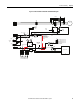
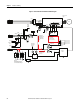
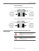
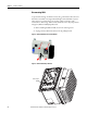
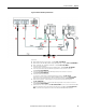
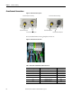
Table Of Contents
- ArmorStart Distributed Motor Controller with EtherNet/IP User Manual
- European Communities (EC) Directive Compliance
- Table of Contents
- Chapter 1
- Product Overview
- Introduction
- Description
- Catalog Number Explanation
- Operation
- Mode of Operation
- Description of Features
- Embedded Switch Technology
- Switched vs. Unswitched Control Power Input/Output (I/O) Connections
- EtherNet/IP™ Ports
- Embedded Web Server
- EtherNet/IP LED Status Indication
- Control Module LED Status and Reset
- Electronic Data Sheet (EDS)
- Fault Diagnostics
- Standard Features
- Factory-Installed Options
- Optional HOA Keypad Configuration (Bulletin 280E/281E only)
- Optional HOA Selector Keypad with Jog Function (Bulletin 284E only)
- Source Brake Contactor and Connector (Bulletin 284E only)
- EMI Filter (Bulletin 284E only)
- Dynamic Brake Connector (Bulletin 284E only)
- IP67 Dynamic Brake Resistor (Bulletin 284E only)
- Output Contactor (Bulletin 284E only)
- Shielded Motor Cable (Bulletin 284E only)
- ArmorStart® EtherNet/ IP Features
- Notes:
- Product Overview
- Chapter 2
- Installation and Wiring
- Receiving
- Unpacking
- Inspecting
- Storing
- General Precautions
- Precautions for Bulletin 280E/281E Applications
- Precautions for Bulletin 284E Applications
- Dimensions
- Mount Orientation
- Operation
- Wiring
- Terminal Designations
- Control Power Wiring
- ArmorStart with EtherNet/IP Internal Wiring
- AC Supply Considerations for Bulletin 284E Units
- Electromagnetic Compatibility (EMC)
- Grounding
- ArmorConnect Power Media
- ArmorConnect Connections
- ArmorConnect Cable Ratings
- Ethernet and I/O Connections
- Power Connections
- Optional Locking Clip
- Installation and Wiring
- Chapter 3
- Chapter 4
- Chapter 5
- Chapter 6
- Chapter 7
- Bulletin 280E/281E/284E Programmable Parameters
- Basic Setup Parameters
- Parameter Groups
- ArmorStart EtherNet/IP Parameters
- Bulletin 280E/281E
- Bulletin 284E
- Basic Status Group
- Produced Assembly Config Group
- Starter Protection Group
- User I/O Configuration Group
- Miscellaneous Configuration Group
- Drive I/O Configuration Group (Bulletin 284E only)
- Drive Display Group (Bulletin 284E only)
- Drive Setup Group (Bulletin 284E only)
- Drive Advanced Setup Group (Bulletin 284E only)
- Clear a Type 1 Fault and Restart the Drive
- Clear an Overvoltage, Undervoltage, or Heatsink OvrTmp Fault without Restarting the Drive
- How StepLogic Works
- StepLogic Settings
- Linear List of Parameters for Bulletin 280E/281E and Bulletin 284E
- Bulletin 280E/281E/284E Programmable Parameters
- Chapter 8
- Chapter 9
- Chapter 10
- Chapter 11
- Chapter 12
- Appendix A
- Applying More Than One ArmorStart Motor Controller in a Single Branch Circuit on Industrial Machinery
- Introduction
- ArmorStart LT Product Family
- Multiple-Motor Branch Circuits and Motor Controllers Listed for Group Installation – General
- Maximum Fuse Ampere Rating According to 7.2.10.4(1) and 7.2.10.4(2)
- Explanatory Example
- Input and Output Conductors of Bulletin 290E and 291E Controllers (a)
- Input and Output Conductors of Bulletin 294E Controllers (b)
- Combined Load Conductors (c)
- Applying More Than One ArmorStart Motor Controller in a Single Branch Circuit on Industrial Machinery
- Appendix B
- CIP Information
- High Level Product Description
- CIP Explicit Connection Behavior
- CIP Object Requirements
- Identity Object
- Assembly Object
- Connection Manager Object
- Discrete Input Point Object
- Discrete Output Point Object
- Parameter Object
- Parameter Group Object
- Discrete Input Group Object
- Discrete Output Group Object
- Control Supervisor Object
- Overload Object
- Device Level Ring (DLR) Object
- Qos Object
- DPI Fault Object
- DPI Alarm Object
- Interface Object
- TCP/IP Interface Object
- Ethernet Link Object
- CIP Information
- Appendix C
- Using DeviceLogix
- DeviceLogix Programming
- DeviceLogix Programming Example
- Import and Export
- Bulletin 284 - VFD Preset Speed Example
- DeviceLogix Ladder Editor Example
- ArmorStart 280 and 281 Status Bits
- Bulletin 280 and 281 ArmorStart Fault Bits
- Bulletin 280 and 281 ArmorStart Outputs
- Bulletin 280 and 281 ArmorStart Produced Network Bits
- Bulletin 284 ArmorStart Status Bits
- Bulletin 284 ArmorStart Fault Bits
- Bulletin 284 ArmorStart Outputs
- Bulletin 284 ArmorStart Produced Network Bits
- Using DeviceLogix
- Appendix D
- Appendix E
- Appendix F
- Back Cover

48 Rockwell Automation Publication 280E-UM001B-EN-P - July 2012
Chapter 2 Installation and Wiring
General safety dictates that all metal parts are connected to earth with separate
copper wire or wires of the appropriate gauge. Most equipment has specific
provisions to connect a safety ground or PE (protective earth) directly to it.
Grounding PE or Ground
The safety ground - PE must be connected to earth ground. This point must
be connected to adjacent building steel (girder, joist), a floor ground rod, bus bar
or building ground grid. Grounding points must comply with national and local
industrial safety regulations or electrical codes. Some codes may require
redundant ground paths and periodic examination of connection integrity.
Grounding Motors
The motor frame or stator core must be connected directly to the PE connection
with a separate ground conductor. It is recommended that each motor frame be
grounded to building steel at the motor.
ArmorConnect Power Media
Description
The ArmorConnect power media offers both three-phase and control power
cable cord set systems including patchcords, receptacles, tees, reducers and
accessories to be utilized with the ArmorStart Distributed Motor Controller.
These cable system components allow quick connection of ArmorStart
Distributed Motor Controllers, reducing installation time. They provide for
repeatable, reliable connection of the three-phase and control power to the
ArmorStart Distributed Motor Controller and motor by providing a plug-and-
play environment that also avoids system mis-wiring. When specifying power
media for use with the ArmorStart Distributed Motor Controllers (Bulletin
280E/281E and Bulletin 284E) use only the Bulletin 280E ArmorConnect
power media.
Refer to the On-Machine Selection Catalog for ordering details. The following
shows example configurations for power, control, and communication media.
IMPORTANT
To avoid electrolytic corrosion on the external earth terminal, avoid spraying
moisture directly on the terminal. When used in washdown environments
apply a sealant or other corrosion inhibitor on the external ground terminal
to minimize any negative effects of galvanic or Electro-chemical corrosion.
Ground connections should be inspected on a regular basis.