
User Manual Owner's manual
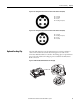
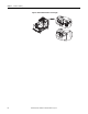
Table Of Contents
- ArmorStart Distributed Motor Controller with EtherNet/IP User Manual
- European Communities (EC) Directive Compliance
- Table of Contents
- Chapter 1
- Product Overview
- Introduction
- Description
- Catalog Number Explanation
- Operation
- Mode of Operation
- Description of Features
- Embedded Switch Technology
- Switched vs. Unswitched Control Power Input/Output (I/O) Connections
- EtherNet/IP™ Ports
- Embedded Web Server
- EtherNet/IP LED Status Indication
- Control Module LED Status and Reset
- Electronic Data Sheet (EDS)
- Fault Diagnostics
- Standard Features
- Factory-Installed Options
- Optional HOA Keypad Configuration (Bulletin 280E/281E only)
- Optional HOA Selector Keypad with Jog Function (Bulletin 284E only)
- Source Brake Contactor and Connector (Bulletin 284E only)
- EMI Filter (Bulletin 284E only)
- Dynamic Brake Connector (Bulletin 284E only)
- IP67 Dynamic Brake Resistor (Bulletin 284E only)
- Output Contactor (Bulletin 284E only)
- Shielded Motor Cable (Bulletin 284E only)
- ArmorStart® EtherNet/ IP Features
- Notes:
- Product Overview
- Chapter 2
- Installation and Wiring
- Receiving
- Unpacking
- Inspecting
- Storing
- General Precautions
- Precautions for Bulletin 280E/281E Applications
- Precautions for Bulletin 284E Applications
- Dimensions
- Mount Orientation
- Operation
- Wiring
- Terminal Designations
- Control Power Wiring
- ArmorStart with EtherNet/IP Internal Wiring
- AC Supply Considerations for Bulletin 284E Units
- Electromagnetic Compatibility (EMC)
- Grounding
- ArmorConnect Power Media
- ArmorConnect Connections
- ArmorConnect Cable Ratings
- Ethernet and I/O Connections
- Power Connections
- Optional Locking Clip
- Installation and Wiring
- Chapter 3
- Chapter 4
- Chapter 5
- Chapter 6
- Chapter 7
- Bulletin 280E/281E/284E Programmable Parameters
- Basic Setup Parameters
- Parameter Groups
- ArmorStart EtherNet/IP Parameters
- Bulletin 280E/281E
- Bulletin 284E
- Basic Status Group
- Produced Assembly Config Group
- Starter Protection Group
- User I/O Configuration Group
- Miscellaneous Configuration Group
- Drive I/O Configuration Group (Bulletin 284E only)
- Drive Display Group (Bulletin 284E only)
- Drive Setup Group (Bulletin 284E only)
- Drive Advanced Setup Group (Bulletin 284E only)
- Clear a Type 1 Fault and Restart the Drive
- Clear an Overvoltage, Undervoltage, or Heatsink OvrTmp Fault without Restarting the Drive
- How StepLogic Works
- StepLogic Settings
- Linear List of Parameters for Bulletin 280E/281E and Bulletin 284E
- Bulletin 280E/281E/284E Programmable Parameters
- Chapter 8
- Chapter 9
- Chapter 10
- Chapter 11
- Chapter 12
- Appendix A
- Applying More Than One ArmorStart Motor Controller in a Single Branch Circuit on Industrial Machinery
- Introduction
- ArmorStart LT Product Family
- Multiple-Motor Branch Circuits and Motor Controllers Listed for Group Installation – General
- Maximum Fuse Ampere Rating According to 7.2.10.4(1) and 7.2.10.4(2)
- Explanatory Example
- Input and Output Conductors of Bulletin 290E and 291E Controllers (a)
- Input and Output Conductors of Bulletin 294E Controllers (b)
- Combined Load Conductors (c)
- Applying More Than One ArmorStart Motor Controller in a Single Branch Circuit on Industrial Machinery
- Appendix B
- CIP Information
- High Level Product Description
- CIP Explicit Connection Behavior
- CIP Object Requirements
- Identity Object
- Assembly Object
- Connection Manager Object
- Discrete Input Point Object
- Discrete Output Point Object
- Parameter Object
- Parameter Group Object
- Discrete Input Group Object
- Discrete Output Group Object
- Control Supervisor Object
- Overload Object
- Device Level Ring (DLR) Object
- Qos Object
- DPI Fault Object
- DPI Alarm Object
- Interface Object
- TCP/IP Interface Object
- Ethernet Link Object
- CIP Information
- Appendix C
- Using DeviceLogix
- DeviceLogix Programming
- DeviceLogix Programming Example
- Import and Export
- Bulletin 284 - VFD Preset Speed Example
- DeviceLogix Ladder Editor Example
- ArmorStart 280 and 281 Status Bits
- Bulletin 280 and 281 ArmorStart Fault Bits
- Bulletin 280 and 281 ArmorStart Outputs
- Bulletin 280 and 281 ArmorStart Produced Network Bits
- Bulletin 284 ArmorStart Status Bits
- Bulletin 284 ArmorStart Fault Bits
- Bulletin 284 ArmorStart Outputs
- Bulletin 284 ArmorStart Produced Network Bits
- Using DeviceLogix
- Appendix D
- Appendix E
- Appendix F
- Back Cover

52 Rockwell Automation Publication 280E-UM001B-EN-P - July 2012
Chapter 2 Installation and Wiring
ArmorConnect Cable Ratings
The ArmorConnect Power Media cables are rated per UL Type TC
600V 90°C Dry 75°C Wet, Exposed Run (ER) or MTW 600V 90°C or
STOOW 105°C 600V - Canadian Standards Association (CSA) STOOW 600V
FT2. For additional information regarding ArmorConnect Power Media refer to
the Industrial Controls Catalog.
Branch Circuit Protection Requirements for ArmorConnect
Three-Phase Power Media
When using ArmorConnect Three-Phase Power Media, fuses or circuit breakers
can be used for the motor branch circuit protective device, for the group motor
installations.
For 25 A rated ArmorConnect cable for trunk and taps:
Circuit Breaker: Suitable for use on a circuit capable of delivering not more than
65 000 RMS symmetrical amperes at 480V AC maximum when protected by
Bulletin 140U-H frame circuit breaker, not rated more than 480V, 100 A and a
maximum interrupting of 65 000 RMS symmetrical amperes Short Circuit
Current Rating (SCCR).
Fusing: Suitable for use on a circuit capable of delivering not more than 65 000
RMS symmetrical amperes (SCCR) at 600V AC maximum when protected by
CC, J, and T class fuses.
For 10 A and 15 A rated ArmorConnect taps:
Circuit Breaker: Suitable for use on a circuit capable of delivering not more than
45 000 RMS symmetrical amperes at 480Y/277V AC maximum when protected
by Cat. No. 140U-D6D3-C30 circuit breaker, not rated more than 480V, 30 A,
having an interrupting rating not less than 45 000 RMS symmetrical amperes,
480Y/277V AC maximum.
Fusing: Suitable for use on a circuit capable of delivering not more than 65 000
RMS symmetrical amperes (SCCR) at 600V AC maximum when protected by
CC, J, and T class fuses, rated 40 A non-time delay or 20 A time delay.
WARNING: The total circuit impedance including each cable assembly's own
impedance, must be low enough to ensure any short-circuit or ground fault current that
can flow through any assembly, will be large enough to operate the magnetic trip of the
Cat. No. 140U-D63-C* circuit breaker. Refer to your local electrical code for acceptable
practices for this evaluation.