
User Manual Owner's manual
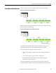
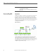
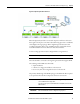

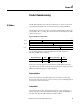
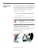
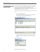
Table Of Contents
- ArmorStart Distributed Motor Controller with EtherNet/IP User Manual
- European Communities (EC) Directive Compliance
- Table of Contents
- Chapter 1
- Product Overview
- Introduction
- Description
- Catalog Number Explanation
- Operation
- Mode of Operation
- Description of Features
- Embedded Switch Technology
- Switched vs. Unswitched Control Power Input/Output (I/O) Connections
- EtherNet/IP™ Ports
- Embedded Web Server
- EtherNet/IP LED Status Indication
- Control Module LED Status and Reset
- Electronic Data Sheet (EDS)
- Fault Diagnostics
- Standard Features
- Factory-Installed Options
- Optional HOA Keypad Configuration (Bulletin 280E/281E only)
- Optional HOA Selector Keypad with Jog Function (Bulletin 284E only)
- Source Brake Contactor and Connector (Bulletin 284E only)
- EMI Filter (Bulletin 284E only)
- Dynamic Brake Connector (Bulletin 284E only)
- IP67 Dynamic Brake Resistor (Bulletin 284E only)
- Output Contactor (Bulletin 284E only)
- Shielded Motor Cable (Bulletin 284E only)
- ArmorStart® EtherNet/ IP Features
- Notes:
- Product Overview
- Chapter 2
- Installation and Wiring
- Receiving
- Unpacking
- Inspecting
- Storing
- General Precautions
- Precautions for Bulletin 280E/281E Applications
- Precautions for Bulletin 284E Applications
- Dimensions
- Mount Orientation
- Operation
- Wiring
- Terminal Designations
- Control Power Wiring
- ArmorStart with EtherNet/IP Internal Wiring
- AC Supply Considerations for Bulletin 284E Units
- Electromagnetic Compatibility (EMC)
- Grounding
- ArmorConnect Power Media
- ArmorConnect Connections
- ArmorConnect Cable Ratings
- Ethernet and I/O Connections
- Power Connections
- Optional Locking Clip
- Installation and Wiring
- Chapter 3
- Chapter 4
- Chapter 5
- Chapter 6
- Chapter 7
- Bulletin 280E/281E/284E Programmable Parameters
- Basic Setup Parameters
- Parameter Groups
- ArmorStart EtherNet/IP Parameters
- Bulletin 280E/281E
- Bulletin 284E
- Basic Status Group
- Produced Assembly Config Group
- Starter Protection Group
- User I/O Configuration Group
- Miscellaneous Configuration Group
- Drive I/O Configuration Group (Bulletin 284E only)
- Drive Display Group (Bulletin 284E only)
- Drive Setup Group (Bulletin 284E only)
- Drive Advanced Setup Group (Bulletin 284E only)
- Clear a Type 1 Fault and Restart the Drive
- Clear an Overvoltage, Undervoltage, or Heatsink OvrTmp Fault without Restarting the Drive
- How StepLogic Works
- StepLogic Settings
- Linear List of Parameters for Bulletin 280E/281E and Bulletin 284E
- Bulletin 280E/281E/284E Programmable Parameters
- Chapter 8
- Chapter 9
- Chapter 10
- Chapter 11
- Chapter 12
- Appendix A
- Applying More Than One ArmorStart Motor Controller in a Single Branch Circuit on Industrial Machinery
- Introduction
- ArmorStart LT Product Family
- Multiple-Motor Branch Circuits and Motor Controllers Listed for Group Installation – General
- Maximum Fuse Ampere Rating According to 7.2.10.4(1) and 7.2.10.4(2)
- Explanatory Example
- Input and Output Conductors of Bulletin 290E and 291E Controllers (a)
- Input and Output Conductors of Bulletin 294E Controllers (b)
- Combined Load Conductors (c)
- Applying More Than One ArmorStart Motor Controller in a Single Branch Circuit on Industrial Machinery
- Appendix B
- CIP Information
- High Level Product Description
- CIP Explicit Connection Behavior
- CIP Object Requirements
- Identity Object
- Assembly Object
- Connection Manager Object
- Discrete Input Point Object
- Discrete Output Point Object
- Parameter Object
- Parameter Group Object
- Discrete Input Group Object
- Discrete Output Group Object
- Control Supervisor Object
- Overload Object
- Device Level Ring (DLR) Object
- Qos Object
- DPI Fault Object
- DPI Alarm Object
- Interface Object
- TCP/IP Interface Object
- Ethernet Link Object
- CIP Information
- Appendix C
- Using DeviceLogix
- DeviceLogix Programming
- DeviceLogix Programming Example
- Import and Export
- Bulletin 284 - VFD Preset Speed Example
- DeviceLogix Ladder Editor Example
- ArmorStart 280 and 281 Status Bits
- Bulletin 280 and 281 ArmorStart Fault Bits
- Bulletin 280 and 281 ArmorStart Outputs
- Bulletin 280 and 281 ArmorStart Produced Network Bits
- Bulletin 284 ArmorStart Status Bits
- Bulletin 284 ArmorStart Fault Bits
- Bulletin 284 ArmorStart Outputs
- Bulletin 284 ArmorStart Produced Network Bits
- Using DeviceLogix
- Appendix D
- Appendix E
- Appendix F
- Back Cover
Rockwell Automation Publication 280E-UM001B-EN-P - July 2012 69
Product Commissioning Chapter 4
Figure 49 - Network Address Example
Valid IP address switch settings range from 001 to 254. When the switches are set
to a valid number, the adapter’s IP address will be 192.168.1.xxx (where xxx
represents the number set on the switches). The adapter’s subnet mask will be
255.255.255.0 and the gateway address is set to 0.0.0.0. A power cycle is required
for any new IP address to take effect.
Note: The upper three octets are fixed. DHCP or the embedded webserver must
be used to configure the IP address to a value other than 192.168.1.xxx.
If the switches are set to an invalid number (such as 000 or a value greater than
254), the adapter will check to see if DHCP is enabled. If DHCP is enabled, the
adapter requests an address from a DHCP server. If DHCP is not enabled, the
adapter will use the IP address (along with other TCP configurable parameters)
stored in non-volatile memory.
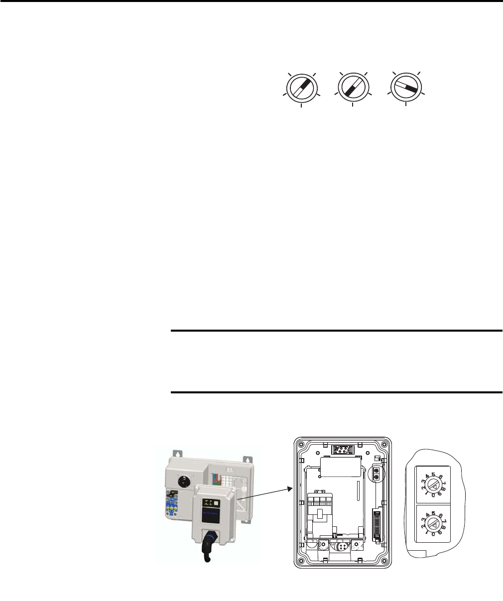
Figure 50 - Rotary Switch on Control Module
IMPORTANT
Refer to Figure 50, the ArmorStart is shipped with the control module rotary
switches set to a value of 99. DO NOT modify this setting. If these are changed
and the unit stops responding, the switches will need to be manually set to node
address 63 and power cycled.
X100
X10
X1
0
8
6
4
2
0
8
6
4
2
0
8
6
4
2
This example shows the
IP address set to 163.
Factory Setting 99