User Manual ArmorStart® LT Distributed Motor Controller Catalog Numbers 290E, 291E, 294E
Important User Information Because of the variety of uses for the products described in this publication, those responsible for the application and use of this control equipment must satisfy themselves that all necessary steps have been taken to assure that each application and use meets all performance and safety requirements, including any applicable laws, regulations, codes and standards.
General Precautions In addition to the precautions listed throughout this manual, the following statements, which are general to the system, must be read and understood. ATTENTION: This manual is intended for qualified service personnel responsible for setting up and servicing these devices. The user must have previous experience with and a basic understanding of electrical terminology, configuration procedures, required equipment, and safety precautions.
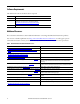
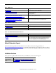
Software Requirements The table lists the versions of software that are required. Software Version RSLinx Classic 2.56 or later RSLogix 5000 17.01 or later Download the most current version of the Add-On Profile from http://www.rockwellautomation.com/support/downloads.html. BOOTP/DHCP Version 2.3 or later Additional Resources These documents and websites contain additional information concerning related Rockwell Automation products. You can view or download publications at http:/www.
Table 2 - ODVA Resources Resource Description http://www.odva.org/ Open DeviceNet Vendors Association (ODVA) website http://www.odva.org/default.aspx?tabid=54 The CIP Advantage website • CIP features and benefits • How to get started Ethernet Media Planning and Installation Manual, ODVA publication http://www.odva.org/Portals/0/Library/Publications_Numbered/ PUB00148R0_EtherNetIP_Media_Planning_and_Installation_Manual.
New Product Satisfaction Return Rockwell Automation tests all of its products to ensure that they are fully operational when shipped from the manufacturing facility. However, if your product is not functioning and needs to be returned, follow these procedures. 6 United States Contact your distributor. You must provide a Customer Support case number (call the phone number above to obtain one) to your distributor to complete the return process.
Summary of Changes New and Updated Information This table contains the changes made to this revision.
Summary of Changes Notes: 8 Rockwell Automation Publication 290E-UM001B-EN-P - June 2012
Preface European Communities (EC) Directive Compliance If this product has the CE mark it is approved for installation within the European Union and European Economic Area (EEA). It has been designed and tested to meet the following directives.
Preface Introduction 10 The ArmorStart LT is an integrated, pre-engineered, motor starting solution designed for use in material handling applications. ArmorStart LT is the latest addition to the ArmorStart portfolio. ArmorStart LT is a leader in the market place given its compact size and high performance features in network, I/O, and motor control. This manual will guide you through the features and functionality when installing the product.
Table of Contents Important User Information . . . . . . . . . . . . . . . . . . . . . . . . . . . . . . . . . . . . . . . 2 General Precautions . . . . . . . . . . . . . . . . . . . . . . . . . . . . . . . . . . . . . . . . . . . . . . . . 3 Software Requirements . . . . . . . . . . . . . . . . . . . . . . . . . . . . . . . . . . . . . . . . . . . . . 4 Additional Resources . . . . . . . . . . . . . . . . . . . . . . . . . . . . . . . . . . . . . . . . . . . . . . . 4 Rockwell Automation Support . . . . .
Table of Contents Optional HOA Selector Keypad with Jog Function(Bulletin 294E only). . . . . . . . . . . . . . . . . . . . . . . . . . . . . . 37 Keypad Local Control . . . . . . . . . . . . . . . . . . . . . . . . . . . . . . . . . . . . . . . . . 37 Keypad and HOA Disable Parameter. . . . . . . . . . . . . . . . . . . . . . . . . . . . 38 Source Brake Contactor and Connector (Bulletin 294E only) . . . . . . . . .38 Chapter 2 Installation and Wiring 12 Receiving . . . . . . . . . . . . . . . . . . . .
Table of Contents Recommended Cord Grips . . . . . . . . . . . . . . . . . . . . . . . . . . . . . . . . . . . . .61 Shield Terminating Connectors . . . . . . . . . . . . . . . . . . . . . . . . . . . . . . . . 61 Electromagnetic Compatibility (EMC) . . . . . . . . . . . . . . . . . . . . . . . . . . . . . 62 General Notes (Bulletin 294E only) . . . . . . . . . . . . . . . . . . . . . . . . . . . . .62 Ethernet, DeviceNet, and I/O Connections . . . . . . . . . . . . . . . . . . . . . . . . .
Table of Contents Bulletin 294E . . . . . . . . . . . . . . . . . . . . . . . . . . . . . . . . . . . . . . . . . . . . . . . . . . . .124 Basic Status Group . . . . . . . . . . . . . . . . . . . . . . . . . . . . . . . . . . . . . . . . . . .124 Trip Status Group . . . . . . . . . . . . . . . . . . . . . . . . . . . . . . . . . . . . . . . . . . . .129 Motor and Control Group . . . . . . . . . . . . . . . . . . . . . . . . . . . . . . . . . . . .133 Speed Control Group . . . . . . . . . . . . . . . . . .
Table of Contents EDS Files . . . . . . . . . . . . . . . . . . . . . . . . . . . . . . . . . . . . . . . . . . . . . . . . . . . .194 CIP Object Requirements. . . . . . . . . . . . . . . . . . . . . . . . . . . . . . . . . . . . . . . . .194 Identity Object. . . . . . . . . . . . . . . . . . . . . . . . . . . . . . . . . . . . . . . . . . . . . . . . . . .195 CLASS CODE 0x0001 . . . . . . . . . . . . . . . . . . . . . . . . . . . . . . . . . . . . . . .195 Message Router . . . . . . . . . . . . . . . . .
Table of Contents Trip and Warning Email Object . . . . . . . . . . . . . . . . . . . . . . . . . . . . . . . . . . .226 CLASS CODE 0x0376 . . . . . . . . . . . . . . . . . . . . . . . . . . . . . . . . . . . . . . .226 Appendix C Using DeviceLogix Support and Feedback 16 Introduction . . . . . . . . . . . . . . . . . . . . . . . . . . . . . . . . . . . . . . . . . . . . . . . . . . . . .229 DeviceLogix Programming . . . . . . . . . . . . . . . . . . . . . . . . . . . . . . . . . . . . . . . .
Chapter 1 Product Overview Description ArmorStart LT is available with Full Voltage, Full Voltage Reversing, or Variable Speed motor control performance. It comes equipped with a UL Listed At-motor disconnect that supports a lock-out tag-out (LOTO) provision. ArmorStart LT is listed as suitable for group installations per UL and can be applied with either branch circuit breaker protection or fuse protection.
Chapter 1 Product Overview Features The ArmorStart LT provides many features and benefits that are unsurpassed in the market place: • Robust IP66, UL Type 4/12 enclosure • UL Listed, Suitable for Group Motor Applications • UL Listed, At-motor disconnect switch • Native support for EtherNet/IP • Embedded dual port ethernet switch • Device Level Ring (DLR) with Beacon frame performance • IEEE 1588 Transparent Clock • RSLogix 5000 Add-On Profile • 6 user configurable I/O points • DeviceLogix • Embedded web
Product Overview Feature Description Chapter 1 Standard Features Across Product Family UL Listed “Suitable for Group Motor Applications” — Where NFPA 70 (NEC) or 79 are required installation standards, this Listing allows two or more motors to be connected to the same branch circuit without individual motor branch short circuit or ground fault protection. Refer to Appendix A for details.
Chapter 1 Product Overview LEDs found on the electronic control module (ECM). If a fault occurs a local fault reset button allows the user to quickly get the process started after corrective action is taken. The user can also configure the embedded webserver to send an email when a fault or warning occurs. Gland plate entrance — ArmorStart LT offers different methods of connecting three-phase, control power, and motor. ArmorStart LT has conduit entrance openings, as standard.
Product Overview Chapter 1 Figure 3 - DLR with Beacon Performance — Fault In this example the fault is precisely identified by the link status message and the supervisor opens the blocked port to allow network traffic to continue normally. IEEE 1588 transparent clock —ArmorStart LT EtherNet/IP version supports the IEEE 1588 transparent clock when used with precision time protocols (PTP).
Chapter 1 Product Overview Factory-Installed Options Internal power supply (IPS) — ArmorStart LT offers the user an optional 24V DC internal power supply. The internal power supply provides all control and I/O power needs and is sourced from the incoming 3-phase power. This eliminates the need to run separate control power to each unit, reducing installation time and cost. The local at-motor disconnect will remove power from the motor terminals and outputs when in the OFF condition.
Product Overview Chapter 1 ArmorStart LT Characteristics Figure 4 - Bulletin 290E/291E ArmorStart LT 0 Off 1 On HOA Keypad (optional) IP Address Switches On/Off Switch Status and Diagnostic LEDs LockOut/TagOut Provision Reset ECM (Electronic Control Module) 6 Configurable I/Os Wiring Access Dual Port EtherNet/IP (This is replaced by a DeviceNet connector, when DeviceNet communication is selected) Protective Earth (PE) Gland Plate – Conduit/Cord Grip or ArmorConnect® Media (optional) Rockwell A
Chapter 1 Product Overview Catalog Number Explanation Examples given in this section are for reference purposes. This basic explanation should not be used for product selection; not all combinations will produce a valid catalog number.
Product Overview Chapter 1 ArmorStart LT Characteristics Figure 5 - Bulletin 294E ArmorStart LT 0 Off 1 On On/Off Switch Wiring Access LockOut/TagOut Provision Hand-Off-Auto Keypad (optional) Reset IP Address Switches Gland Plate – Conduit/Cord Grip or ArmorConnect Media (optional) Status and Diagnostic LEDs ECM (Electronic Control Module) Protective Earth (PE) Bottom View Rockwell Automation Publication 290E-UM001B-EN-P - June 2012 6 Configurable I/Os Dual Port EtherNet/IP (This is replaced b
Chapter 1 Product Overview Catalog Number Explanation Examples given in this section are for reference purposes. This basic explanation should not be used for product selection; not all combinations will produce a valid catalog number.
Product Overview Group Motor Installations for USA and Canada Markets The ArmorStart LT Distributed Motor controllers are listed for use with each other in group installations per NFPA 79, Electrical Standard for Industrial Machinery and NFPA 70, the National Electrical Code. When applied according to the group motor installation requirements, two or more motors are permitted on a single branch circuit. Group Motor Installation has been successfully used for many years in the USA and Canada.
Chapter 1 Product Overview Figure 7 - Control Circuit Wiring Diagram — Multiple External Power Supplies ArmorStart LT L1 L2 L3 Switched Control Power Off * Unswitched Control Power Disconnect EtherNet Comms Inputs Motor Control Outputs Motor Controller A1 T1 T2 A2 A3 T3 * Control power output is determined by disconnect status Class 2 External Switched 24VDC Power Supply Class 2 External Unswitched 24VDC Power Supply L + 24VDC - N L + 24VDC - N Figure 8 - Control Circuit Wiring
Product Overview Chapter 1 Motor Circuit The ArmorStart LT Distributed Motor Controllers are rated to operate the following types of three-phase squirrel-cage induction motors: Bulletin 290E/291E: 0.5 Hp (0.37 kW) to 5 Hp (3 kW) @ 480/277V AC Bulletin 294E: 0.5 Hp (0.37 kW) to 2 Hp (1.5 kW) @ 480/277V AC Local I/O The ArmorStart LT provides as standard, 6 user configurable I/O points. By default, all points are configured as an Input.
Chapter 1 Product Overview Overload Protection The ArmorStart LT Distributed Motor Controller incorporates, as standard, electronic motor overload protection. This overload protection is accomplished electronically with an I2t algorithm. The ArmorStart LT’s overload protection is programmable via the communication network, providing the user with greater flexibility. The Bulletin 290E/291E includes programmable overload Class 10, 15, and 20 protection.
Product Overview Mode of Operation Bulletin 294E Chapter 1 Sensorless Vector Performance Using a distributed AC drive to operate mechanical equipment at optimum speed helps reduce energy costs and eliminates mechanical wear and tear that can occur in the mechanical parts. The advance monitoring found in ArmorStart LT protects critical equipment against unplanned downtime with advanced diagnostics and notification of irregular operating parameters.
Chapter 1 Product Overview Status LEDs and Reset Figure 12 - Status, Diagnostic LEDs, and Reset ArmorStart LT provides comprehensive status and diagnostics via 12 individually marked LEDs shown in Figure 12, located on the ECM module. In addition, a local reset is provide for clearing of faults. Table 5 details the diagnostic and status LEDs.
Product Overview Chapter 1 Electronic Data Sheet (EDS) ArmorStart LT EtherNet/IP has an embedded electronic data sheet. An EDS consists of specially formatted text files, as defined by the CIP™. EDS files contain details about the readable and configurable parameters of the EtherNet/IP device. They also provide information about the I/O connections that the device supports and the content of the associated data structures.
Chapter 1 Product Overview Fault Diagnostics Fault diagnostics capabilities built in the ArmorStart LT Distributed Motor Controller are designed to help you pinpoint a problem for easy troubleshooting and quick re-starting. Protection Faults Protection faults will be generated when potentially dangerous or damaging conditions are detected. Protection faults are also known as “trips” or “faults”.
Product Overview Optional HOA Selector Keypad Optional HOA Keypad Configuration (Bulletin 290E/291E only) Chapter 1 Keypad Local Control The HOA Selector Keypad allows for local start/stop/jog control in forward/ reverse motor direction. If two buttons are pressed simultaneously, this action is ignored by the device unless one of the buttons is the OFF button. If the OFF button is pressed at any time, the unit will go to the off state.
Chapter 1 Product Overview Bulletin 290E With the KeypadMode parameter (parameter 66) set to 1 = Maintained, pressing the buttons reacts like a maintained switch. Current Mode Key Press OFF HAND AUTO AUTO Auto Mode — Motor Off — — HAND If no fault, Motor On — — OFF — Motor turns Off Motor turns Off FAULT PRESENT — Motor turns Off Motor turns Off With the KeypadMode parameter (parameter 66) set to 0 = Momentary, pressing the buttons reacts like a momentary switch.
Product Overview Optional HOA Selector Keypad with Jog Function (Bulletin 294E only) Chapter 1 The HOA Selector Keypad with Jog function allows for local start/stop control with capabilities to jog in forward/reverse motor directions. Figure 15 - Bulletin 294E Jog/Forward/Reverse HOA Keypad Local Control With the KeypadMode parameter (parameter 66) set to 1 = Maintained, pressing the buttons reacts like a maintained switch.
Chapter 1 Product Overview Keypad Disable Parameter “Keypad Disable”, parameter 67, only inhibits the “HAND”, “FWD”, “REV” and “JOG” buttons on the HOA keypad. The “OFF” and “AUTO” buttons are always enabled, even if parameter 67 is set to “1=Disable”. The keypad OFF button can not be disabled. Source Brake Contactor and Connector (Bulletin 294E only) An internal contactor is used to switch the electromechanical motor brake On/Off.
Chapter 2 Installation and Wiring Receiving It is the responsibility of the user to thoroughly inspect the equipment before accepting the shipment from the freight company. Check the item(s) received against the purchase order. If any items are damaged, it is the responsibility of the user not to accept delivery until the freight agent has noted the damage on the freight bill. Should any concealed damage be found during unpacking, it is also the responsibility of the user to notify the freight agent.
Chapter 2 Installation and Wiring Installation Precautions The following statements must be read and understood. ATTENTION: The earth ground terminal shall be connected to a solid earth ground via a low-impedance connection. ATTENTION: Copper ground conductors are recommended. The ArmorStart LT external protective earth (PE) pad is aluminum. Refer to your local electrical installation standard for proper bonding and protection when dissimilar metals are used.
Installation and Wiring Chapter 2 Dimensions are shown in millimeters (inches). Dimensions are not intended to be used for manufacturing purposes. All dimensions are subject to change. Dimensions Figure 16 - Dimensions for Bulletin 290E/291E 130 (5.1) 260 (10.2) 166,5 (6.6) 217,83 (8.6) 202,05 (8.0) 170 (6.7) 152,65 (6.0) 65 (2.6) Front View Right Side View Line Control Motor 37 (1.5) 37 (1.5) 57,13 (2.3) 57,13 (2.3) 38.49 (1.5) 38,49 (1.5) 1 in. conduit opening 24,25 48,5 (1.0) (1.
Chapter 2 Installation and Wiring Figure 17 - Dimensions for Bulletin 294E 381 (15.0) 240 (9.4) 219,32 (8.6) 206,43 (8.1) 170 (6.7) 120 (4.7) Front View 202,27 (8.0) 37 (1.5) 92,9 (3.7) 38.49 (1.5) 24,25 (1.0) 1 in. conduit opening 48,5 0.75 in. conduit opening (1.9) Right Side View Conduit Gland Entrance - Bottom View Line Motor Motor 37 (1.5) 92,9 (3.7) 24,25 (1.0) Line Motor Control 37 (1.5) 37 (1.5) 92.9 (3.7) 38,61 (1.5) Control Line Source Brake 92,9 (3.7) 38,55 (1.
Installation and Wiring Chapter 2 Dimensions are shown in millimeters (inches). Dimensions are not intended to be used for manufacturing purposes. All dimensions are subject to change. Figure 18 - ArmorStart LT Gland Plate Matrix G1 Conduit Standard U.S. Trade Knock-outs G3 Conduit Daisy Chaining IP66 Metric Fittings G2 Media Dia. 25.5 mm Dia. 20.5 mm No Internal Power Supply No Source Brake Source Brake No Internal Power Supply Cat. No. 290-G3-A2 1.00 in. (25.4 mm) 0.75 in. (19.05 mm) 0.75 in.
Chapter 2 Installation and Wiring Figure 20 - Gland Connection Wiring Terminal Detail 44 The power, control, and ground wire capacity and the tightening torque requirements are shown in Table 8. The maximum number of connections per terminal are shown in Table 7. As shown in Figure 21 all the terminals are found in the wiring area. Access can be gained by removing the terminal access cover plate.
Installation and Wiring Chapter 2 Figure 21 - ArmorStart LT Power and Control Terminals A1 L1 L2 L3 T1 T2 T3 A2 A3 PE B1 B2 Table 7 - Power, Control, and Ground Terminal Designations Wire Strip Length 0.35 ± 0.01 in. (9 ± 0.
Chapter 2 Installation and Wiring Table 8 - Power, Control, and Ground Wire Capacity and the Tightening Torque Requirements Wire Size Power Terminals Motor Terminals Control Terminals PE/Ground Source Brake (Bulletin 294) (2) #18…#10 AWG (0.8…5.2 mm2) per terminal Tightening Torque 10.6 +/– 2 lb•in (1.2 +/– 0.2 N•m) Wire Size #18…#10 AWG (0.8…5.2 mm2) per terminal Tightening Torque 10.6 +/– 2 lb•in (1.2 +/– 0.2 N•m) Wire Size (2) #18…#10 AWG (0.8…5.2 mm2) per terminal Tightening Torque 10.
Installation and Wiring Typical System Example Chapter 2 The primary function of ArmorStart LT is to control and protect a three-phase squirrel cage induction motor. Three-phase power enters through terminals that are connected to a manually operated disconnect switch. The three-phase power may also connect internally to an optional three-phase to 24V DC power supply (IPS). Wired in series with the disconnect is an electrically operated contactor or a variable frequency drive.
Chapter 2 Installation and Wiring ArmorConnect Media For greater flexibility and faster installations the user may also use ArmorConnect media for a complete plug-n-play solution. This solution provides plug-in style stop stations, as shown in Figure 23. The ArmorConnect power media offers both three-phase and control power cable cord set systems. These include patchcords, receptacles, tees, reducers and accessories to be utilized with the ArmorStart LT Distributed Motor Controller.
Installation and Wiring Chapter 2 6. The E-stop Out tee (Cat. No.: 898N-653ES-NKF) is used with cordset or patchcord to connect to the ArmorStart Distributed Motor Controller. 7. Control Power Receptacles – Female receptacles are a panel mount connector with flying leads (Cat. No.: 888N-D65AF1-*) 8. Three-Phase Power Trunk – Patchcord cable with integral female or male connector on each end (Example Cat. No.:280-PWRM35A-M*) 9.
Chapter 2 Installation and Wiring at 480Y/277 VAC maximum when protected by Cat. No.140U-D6D3-C30 circuit breaker, refer to the Specifications, Chapter 6. WARNING: The total circuit impedance including each cable assembly's own impedance, must be low enough to ensure any short-circuit or ground fault current that can flow through any assembly, will be large enough to operate the magnetic trip of the Cat. No. 140U-D63-C* circuit breaker.
Installation and Wiring Chapter 2 Figure 25 - Bulletin 290E Full Voltage At Motor Disconnect DOL Overload L1 T1 L2 T2 L3 T3 Disconnect Status Motor Fwd Status Fwd Control Disconnect State, Voltage Monitoring and Power Loss PE Switched (SW) Common UnSwitched (USW) Power Conditioning Board A1 Internal Outputs Micro Internal Inputs EtherNet/IP Logic Power Loss A2 External External Outputs Inputs A3 Sensor Voltage Sinking Input or Sourcing output 1 4 5 2 3 Common 6-User Configurable
Chapter 2 Installation and Wiring Figure 27 - Bulletin 294E VFD At Motor Disconnect L1 L1 T1 L2 T2 L3 TB2 1 T3 L2 L3 Disconnect Status Drive Enable Power Conditioning Board PE Switched A1 (SW) A2 Common) A3 UnSwitched (USW) T2 Motor T3 J3 11 Disconnect State, Voltage Monitoring and Power Loss T1 Internal Outputs Micro Fan Internal Inputs EtherNet/IP Logic Power Loss External External Outputs Inputs Sinking Input or Sourcing output Sensor Voltage 1 5 4 2 3 Common 6-User Configu
Installation and Wiring Chapter 2 Figure 29 - Bulletin 290E Full Voltage with -IPS At Motor Disconnect DOL Overload L1 T1 L2 T2 L3 T3 Disconnect Status Motor Fwd Status Fwd Control Disconnect State, Voltage Monitoring and Power Loss 1 Internal Outputs Micro Internal Inputs EtherNet/IP Logic PE Power Loss 4 1 2 3 External External Outputs Inputs Sensor Voltage Sinking Input or Sourcing output 1 2 5 4 3 Common 6-User Configurable I/O Points Figure 30 - Bulletin 291E Full Voltage Re
Chapter 2 Installation and Wiring L1 At Motor Disconnect L1 T1 L2 T2 L3 TB2 1 T3 L2 L3 Disconnect Status Drive Enable T2 T3 Motor J3 11 Disconnect State, Voltage Monitoring and Power Loss T1 Internal Outputs Micro Fan Internal Inputs EtherNet/IP Logic PE Power Loss 4 1 2 3 External External Outputs Inputs Sinking Input or Sourcing output Sensor Voltage 1 4 2 5 3 Common 6-User Configurable I/O Points Figure 32 - Bulletin 294E VFD with -IPS, -SB At Motor Disconnect L1 L2 L3 Dis
Installation and Wiring Group Motor Installations for USA and Canada Markets When ArmorStart LT is applied according to group motor installation requirements, two or more motors of any rating or controller type, are permitted on a single branch circuit. Group Motor Installation has been successfully used for many years in the USA and Canada.
Chapter 2 Installation and Wiring Service Space The working space around the ArmorStart LT can be minimized as the ArmorStart LT does not require examination, adjustment, servicing or maintenance while energized. In lieu of this service, the ArmorStart LT is meant to be unplugged and replaced after proper lock-out/tag-out procedures have been employed. Hand Operation (HOA) Considerations The Hand/Off/Auto (HOA) is a factory-installed option that the user may select.
Installation and Wiring Grounding Chapter 2 An effectively grounded product is one that is “intentionally connected to earth through a ground connection or connections of sufficiently low impedance and having sufficient current-carrying capacity to prevent the buildup of voltages which may result in undue hazard to connected equipment or to persons” (as defined by the US National Electric Code NFPA70, Article 100B).
Chapter 2 Installation and Wiring Power Distribution The type of transformer and the connection configuration feeding an ArmorStart LT Bulletin 294E plays an important role in its performance and safety. Delta/Wye with Grounded Wye Neutral Figure 33 - Delta/Wye with Grounded Wye Neutral is the most common type of distribution system. The grounded neutral provides a direct path for common mode current caused by the drive output.
Installation and Wiring Chapter 2 refer to the recommended EMI/RFI cord grip accessory or quick disconnect shielded motor cable. Contact your local sales representative for details. If however, the customer specifications require input line reactors or transformers, the recommendation is to group the ArmorStarts at the distribution panel under one line reactor (not individual reactors or transformers).
Chapter 2 Installation and Wiring Figure 34 - Unshielded Multi-Conductor Cable Filler PVC Outer Sheath W B R G Single Ground Conductor Shielded Cable Shielded cable contains all of the general benefits of multi-conductor cable with the added benefit of a copper braided shield that can contain much of the noise generated by a typical AC Drive.
Installation and Wiring Chapter 2 Recommended Cord Grips The following are recommended cord grips to be used for ArmorStart LT installations. Table 9 - Cord grip for Motor, Power, and Control Recommended Thomas and Betts Cord Grips for G1 and G3 Glands. Thomas and Betts Part Nos. Gland Knockout Size Cable Diameter Range (in.2) Cord Grip Sealing Ring Lock Nut Motor/Source Brake G1 0.75 in. 0.500…0.750 2932NM 5263 142TB Motor/Source Brake G1 0.75 in. 0.660…0.
Chapter 2 Installation and Wiring Figure 36 - Terminating the Shield with a Connector Metal connector body makes direct contact with the braid wires U (T1) Braid wires pulled back in a 360° pattern around the ground cone of the connector Ground Bushing V (T2) W (T3) PE One or More Ground Leads Metal locknut bonds the connector to the panel Drain wires pulled back in a 360° pattern around the ground cone of the connector ATTENTION: Shielded connector or motor cable is mandatory for CE compliant inst
Installation and Wiring Chapter 2 ATTENTION: RFI Filter Grounding. Due to the presence of an integral EMI filter, this product may draw more that 3.5 mA of leakage current. The controller must only be used in installations with grounded AC supply systems and be permanently installed and solidly grounded (bonded) to the building power distribution ground. Grounding should not include any form of plug or socket that would permit inadvertent disconnection.
Chapter 2 Installation and Wiring ArmorConnect Power Media Receptacles ArmorStart LT utilizes a M22 male receptacle for power inputs and a M22 female receptacle for motor or motor brake output.
Installation and Wiring Optional Locking Clip Chapter 2 The locking clip is an optional device that can be used, if desired. The clam shell design clips over power quick disconnect connections to limit customer access to disconnection. Figure 37 - SHOCK HAZARD: DO NOT connect or disconnect power or motor connections while power is applied to ArmorStart LT. Proper Lock-Out Tag-Out procedures should be followed to reduced the risk of severe injury.
Chapter 2 Installation and Wiring Notes: 66 Rockwell Automation Publication 290E-UM001B-EN-P - June 2012
Chapter 3 Product Commissioning The IP address identifies each node on the IP network (or system of connected networks). Each TCP/IP node on a network must have a unique IP address. IP Address The IP address is 32 bits long and has a net ID part and Host ID part. Networks are classified A, B, C, (or other). The class of the network determines how an IP address is formatted.
Chapter 3 Product Commissioning Configuring EtherNet/IP Address Before using the ArmorStart LT, you may need to configure an IP address, subnet mask, and optional Gateway address. The rotary network address switches found on the front of the ECM, are set to 999 and DHCP is enabled as the factory default.
Product Commissioning Chapter 3 255.255.255.0 and the gateway address is set to 0.0.0.0. A power cycle is required for any new IP address to take effect when the switches are used. ATTENTION: To avoid unintended operation, the ArmorStart LT must be assigned a fixed IP address. If a DHCP server is used, it must be configured to assign a fixed IP address for ArmorStart LT. Failure to observe this precaution may result in unintended machine motion or loss of process control.
Chapter 3 Product Commissioning Using the Rockwell Automation BootP/DHCP Utility The Rockwell Automation BootP/DHCP utility is a stand alone program that incorporates the functionality of standard BootP/DHCP software with a user friendly graphical interface. It is located in the Utils directory on the RSLogix 5000 installation CD. The ArmorStart LT must have DHCP enabled (factory default) to use the utility. To configure your adapter using the BootP/DHCP utility, perform the following steps: 1.
Product Commissioning Chapter 3 3. Enter the IP Address you want to assign to the device, and click OK. The device is added to the Relation List, displaying the Ethernet Address (MAC) and corresponding IP Address, Hostname, and Description (if applicable). Figure 43 - Relation List When the address displays in the IP Address column in the Request History section, it signifies that the IP address assignment has been made. 4.
Chapter 3 Product Commissioning Figure 44 - Enable DHCP Button Save the Relation List You can save the Relation List to use later. To save the Relation List perform the following steps: 1. Select Save As... from the File menu. Figure 45 - Save Relation List You will see the Save As Dialog.
Product Commissioning Chapter 3 Figure 46 - Save As Dialog Box 2. Select the folder you want to Save in. 3. Enter a File name for the Relation List (for example, Control System Configuration), and click Save. You can leave the Save as type at the default setting: Bootp You can then open the file containing the Relation List at a later session. When DHCP is enabled (factory default Enabled), the unit will request its network configuration from a DHCP/BOOTP server.
Chapter 3 Product Commissioning Embedded Web Server The embedded web server is used to access configuration and status data. IMPORTANT The user should set the password to a unique value for authorized personnel. If the login and password are lost you will need to reset the device to the factory defaults, which results in losing its configuration. To access the internal web browser, open your computer’s internet browser and enter the IP address of the desired ArmorStart LT (for example, 192.168.1.1).
Product Commissioning Chapter 3 Network Configuration To access the network configuration, you will be prompted to login to the Administrative Setting. Figure 48 - Enter Network Password The user will be prompted to enter the default User Name (Administrator). The factory default password is blank. The user is expected to change the password to avoid unauthorized access. Figure 49 - Network Configurations From this screen you can change the Ethernet Configuration.
Chapter 3 Product Commissioning Parameter Configuration ArmorStart LT embedded web server provides the user the ability to view and modify the device configuration without having to access RSLogix 5000. To view the device configuration from the web server, select the parameters folder. Figure 50 - In the figure above, the Starter Setup parameters are viewed. To modify a parameter the user will click the “Edit” button.
Product Commissioning Chapter 3 Figure 52 - E-mail Notification Configuration E-mail triggers: • when a trip occurs • when a trip is cleared • when a warning occurs • when a warning is cleared IMPORTANT “Cleared Event” e-mails will only be sent when all events have been cleared and if a trip event e-mail has previously been sent. The following is an example trip e-mail: Subject: ArmorStart LT 291E 1.1-7.6A has detected an Overload Trip Body: Trip Snapshot: SnapShotL1Amps: 1.
Chapter 3 Product Commissioning How to Add a New Module Using the Add-On Profile ArmorStart LT is provided with an Add-On Profile (AOP). An Add-on profile streamlines the programming and installation by eliminating the task of individually configuring the device tags and providing an easy to use configuration interface. In addition, the copy and paste function allows easy configuration of multiple ArmorStart LTs with RSLogix™ 5000 revision 17.01 or later.
Product Commissioning Chapter 3 3. From the list of modules find the ArmorStart LT using the catalog number. The AOP will include all options therefore the list will only display the base catalog number. 4. The “General” page is displayed. Enter a descriptive name for the ArmorStart LT. 5. In the “General” page enter the ArmorStart LT IP address. The “Private Address” corresponds to the local IP address configurations using the switches.
Chapter 3 Product Commissioning • User I/O Configuration: Specify the Input or Output use for each I/O point • Keypad Option: Is product supplied with this option • Electro-Mechanical Brake Option: Is product supplied with this option The figure below is an example of the Module Definition page. Electronic Keying The electronic keying feature automatically compares the expected module, as shown in the RSLogix 5000 I/O Configuration tree, to the physical module before I/O communication begins.
Product Commissioning Chapter 3 Connections Two Class 1 connections for I/O transfer will be supported and six Class 3 explicit connections will be supported. The Class 1 connections are: • Data • Listen Only Only one Data connection is allowed. A maximum of two Listen Only connections are supported (shared with the Data connection). This connection type is dependent on another connection to exist. If that connection (Data) is closed, the listen only connection shall be closed as well.
Chapter 3 Product Commissioning HOA Keypad Option ArmorStart LT units are available with or without an HOA Keypad. The user will specify either “Installed” or “Not Installed”. When a unit is provided without the HOA keypad this setting should be set to “Not Installed” which removes the keypad parameters. Source Brake, Electro-Mechanical Brake Option ArmorStart LT units are available with or without an electromechanical (EM) brake. The user will select either “Installed” or “Not Installed”.
Product Commissioning Chapter 3 Once complete the new ArmorStart LT will appear in the Ethernet tree. If there are multiple ArmorStart LTs with similar configurations, utilize the copy-paste function and update only those parameters that change between units. The final step is to download your project to the controller and the ArmorStart LT. Define the path to the PLC and then download.
Chapter 3 Product Commissioning Catalog Number AOP Description 294E-FVD1P5P ArmorStart LT VFD, 480V AC, 0.5 Hp, IPS 294E-FVD2P5P ArmorStart LT VFD, 480V AC, 1 Hp, IPS 294E-FVD4P2P ArmorStart LT VFD, 480V AC, 2 Hp, IPS The AOP presents an organized view of parameters within groups and specific functional pages. All of the parameters are distributed within the AOP pages. Each page includes basic information that must be reviewed by the user.
Product Commissioning Chapter 3 Auto-Generated Tags After you install and configure the AOP, the controller tags are generated. The tag names are descriptive and automatically generated. This greatly simplifies programming. The figure below shows an example of the auto-generated tags for ArmorStart LT. The following tables provide more clarification regarding the Produce and Consume assemblies and how they correlate with the auto-generated names.
Chapter 3 Product Commissioning Table 10 - Default Consume Assembly for Bulletin 294E Instance 154 “Drive Cmd” – Default Consumed Assembly for Bulletin 294 Starters Byte Bit 7 Bit 6 Bit 5 0 1 Decel2 Accel2 Bit 4 Bit 3 Bit 2 Bit 1 Bit 0 JogReverse JogForward ResetFault RunReverse RunForward Out04 Out03 Out02 Out01 Out00 Out05 2 CommandFreq (Low) (xxx.x Hz) 3 CommandFreq (High) (xxx.
Product Commissioning Device Name Name Logix Tag Name Data Type Chapter 3 Style ASLT_DEMO Pt14DeviceIn ASLT_DEMO:O.Pt14DeviceIn BOOL Decimal ASLT_DEMO Pt15DeviceIn ASLT_DEMO:O.Pt15DeviceIn BOOL Decimal ASLT_DEMO Int00DeviceIn ASLT_DEMO:O.Int00DeviceIn BOOL Decimal Bit 2 Bit 1 Bit 0 Table 12 - Default Produce Assembly for Bulletin 294E Instance 156 “Drive Status” - Produced Assembly for Bulletin 294 Starters Byte Bit 7 Bit 6 Bit 5 Bit 4 Bit 3 0 Reserved - (name):I.
Chapter 3 Product Commissioning Table 13 - Bulletin 294E Produced Assembly Status Tags Device Name 88 Name Logix Tag Name Data Type Style ASLT_DEMO Fault ASLT_DEMO:I.Fault DINT Binary ASLT_DEMO TripPresent ASLT_DEMO:I.TripPresent BOOL Decimal ASLT_DEMO WarningPresent ASLT_DEMO:I.WarningPresent BOOL Decimal ASLT_DEMO RunningForward ASLT_DEMO:I.RunningForward BOOL Decimal ASLT_DEMO RunningReverse ASLT_DEMO:I.RunningReverse BOOL Decimal ASLT_DEMO Ready ASLT_DEMO:I.
Product Commissioning Device Name Data Type Chapter 3 Name Logix Tag Name Style ASLT_DEMO DCBusVoltage ASLT_DEMO:I.DCBusVoltage INT Decimal ASLT_DEMO SwitchedVoltageLevel ASLT_DEMO:I.SwitchedVoltageLevel INT Decimal ASLT_DEMO UnswitchedVoltageLevel ASLT_DEMO:I.UnswitchedVoltageLevel INT Decimal ASLT_DEMO InternalFanRPM ASLT_DEMO:I.InternalFanRPM INT Decimal ASLT_DEMO OperatingHours ASLT_DEMO:I.OperatingHours INT Decimal ASLT_DEMO DriveTemperature ASLT_DEMO:I.
Chapter 3 Product Commissioning Table 15 - Bulletin 294E Produced Assembly/Status Tag Explanation 90 Device Input Status Tags Tag Description/Use Fault Communication fault between PLC and device (all 1s = fault, all 0s = normal) TripPresent Fault exists within unit WarningPresent Warning of potential fault RunningForward Motor commanded to run forward RunningReverse Motor commanded to run reverse Ready Control and 3-phase power present NetworkControlStatus Start and Stop command comes fro
Product Commissioning Device Input Status Tags Chapter 3 Tag Description/Use DCBusVoltage VFD DC bus voltage — Parameter 5 SwitchedVoltageLevel Switched control power voltage — Parameter 11 UnswitchedVoltageLevel Unswitched control power voltage — Parameter 12 InternalFanRPM VFD fan speed — Parameter 13 OperatingHours Elapse run hours — Parameter 14 DriveTemperature VFD internal temperature — Parameter 15 TripStatus Bit enumerate trip status — Parameter 16 WarningStatus Bit enumerate warn
Chapter 3 Product Commissioning Table 16 - Default Consume Assembly for Bulletin 290E/291E Instance 150 “Starter Cmd” - DeviceLogix Consumed Assembly for Bulletin 290 / 291 Starters Byte Bit 7 Bit 6 Bit 5 Bit 4 Bit 3 0 1 Bit 2 Bit 1 Bit 0 ResetFault RunReverse RunForward Out05 Out04 Out03 Out02 Out01 Out00 2 Pt07DeviceIn Pt06DeviceIn Pt05DeviceIn Pt04DeviceIn Pt03DeviceIn Pt02DeviceIn Pt01DeviceIn Pt00DeviceIn 3 Pt15DeviceIn Pt14DeviceIn Pt13DeviceIn Pt12DeviceIn Pt11Devic
Product Commissioning Chapter 3 Table 18 - Bulletin 290E/291E Starters Starter Stat Produced Assembly Instance 152 “Starter Stat” - Produced Assembly for Bulletin 290E / 291E Starters Byte Bit 7 Bit 6 Bit 5 Bit 4 Bit 3 Bit 2 Bit 1 Bit 0 RunningReverse RunningForward WarningPresent TripPresent KeyPadHand KeyPadOff KeyPadAuto DLXEnabled 0 Reserved - (name):I.ConnectionFault ➊ 1 Reserved - (name):I.ConnectionFault ➊ 2 Reserved - (name):I.ConnectionFault ➊ Reserved - (name):I.
Chapter 3 Product Commissioning Device Name 94 Name Logix Tag Name Data Type Style DEMO_REV DeviceLogixEnabled DEMO_REV:I.DeviceLogixEnabled BOOL Decimal DEMO_REV KeypadAuto DEMO_REV:I.KeypadAuto BOOL Decimal DEMO_REV KeypadOff DEMO_REV:I.KeypadOff BOOL Decimal DEMO_REV KeypadHand DEMO_REV:I.KeypadHand BOOL Decimal DEMO_REV DisconnectClosed DEMO_REV:I.DisconnectClosed BOOL Decimal DEMO_REV Pt00Data DEMO_REV:I.Pt00Data BOOL Decimal DEMO_REV Pt01Data DEMO_REV:I.
Product Commissioning Chapter 3 The following table provides a brief explanation for the tag function: Table 20 - Bulletin 290E/291E Consume Assembly Command Tag Explanation Device Output Command Tags Tag Description/Use RunForward Command VFD forward RunReverse Command VFD reverse ResetFault Fault reset Pt00Data If user defined as output, commnd output ON Pt01Data If user defined as output, commnd output ON Pt02Data If user defined as output, commnd output ON Pt03Data If user defined as ou
Chapter 3 Product Commissioning Table 21 - Bulletin 290E/291E Produced Assembly Status Tag Explanation 96 Device Input Status Tags Tag Description/Use Fault Communication fault between PLC and device (all 1s = fault, all 0s = normal) TripPresent Fault exists within unit WarningPresent Warning of potential fault RunningForward Motor commanded to run forward RunningReverse Motor commanded to run reverse Ready Control and 3-phase power present CurrentFlowing Current is passing to motor Devi
Product Commissioning Device Input Status Tags Chapter 3 Tag Description/Use UnswitchedVoltageLevel Unswitched control power voltage — Parameter 12 TripStatus Bit enumerate trip status — Parameter 16 WarningStatus Bit enumerate warning status — Parameter 17 Rockwell Automation Publication 290E-UM001B-EN-P - June 2012 97
Chapter 3 Product Commissioning Notes: 98 Rockwell Automation Publication 290E-UM001B-EN-P - June 2012
Chapter 4 Bulletin 290E/291E/294E Programmable Parameters Electronic Data Sheet (EDS) When a 3rd party PLC is used, an embedded EDS file can be uploaded directly from the ArmorStart LT. This allows device configuration through 3rd party tools. EDS files are also available on the internet at: http://www.ab.com/ networks/eds. Basic Setup Parameters When the RSLogix AOP is not used, Table 22 lists the minimum setup configurations required for Bulletin 290E/291E or Bulletin 294E.
Chapter 4 Bulletin 290E/291E/294E Programmable Parameters Parameter Groups Bulletin 290E/291E Units Bulletin 294E Units Common to Bulletin 290E/291E and Bulletin 294E Units Bulletin 290E/291E Units Trip Status Basic Config Basic Status 1 PhaseL1Current 2 PhaseL2Current 3 PhaseL3Current 4 AverageCurrent 5%ThermalUtilized 6 StarterStatus 7 StarterCommand 8 AuxIOStatus 9 NetworkStatus 10 DLXControlStatus 11 OutputSourceV 12 SensorSourceV 13 Reserved 14 Reserved 15 Reserved 100 1 OutputFreq 2 CommandF
Bulletin 290E/291E/294E Programmable Parameters Common to Bulletin 290E/291E and Bulletin 294E Units Bulletin 294E Units Motor and Control 28 MotorNPVolts 29 MotorNPHertz 30 MotorOLCurrent 31 CurrentLimit 32 StopMode Bulletin 290E/291E Units Chapter 4 Speed Control 33 SpeedReference 34 MinimumFreq 35 MaximumFreq 36 AccelTime1 37 DecelTime1 38 SCurvePercent 39 JogFrequency 40 JogAccelDecel Starter Protection 41 ProtFltResetMode 42 ProtectFltEnable 43 WarningEnable 44 ProtectFltReset 45 RunNetFltAction
Chapter 4 Bulletin 290E/291E/294E Programmable Parameters ArmorStart LT EtherNet/IP Parameters Introduction This chapter describes each programmable parameter and its function. Parameter Programming Each Distributed Motor Controller type will have a common set of parameters and a set of parameters that pertain to the individual starter type. Parameters 41…68 are common to all ArmorStart LTs.
Bulletin 290E/291E/294E Programmable Parameters PhaseL3Current This parameter determines the actual Phase L3 current. AverageCurrent This parameter determines the average of 3 Phase currents. %ThermalUtilized This parameter determines the percent of Thermal Capacity used. StarterStatus This parameter provides the status of the starter. Parameter Number 3 Access Rule GET Data Type INT Group Basic Status Units x.
Chapter 4 Bulletin 290E/291E/294E Programmable Parameters Bit 15 14 13 12 11 10 9 8 6 5 4 3 2 1 Function 0 — — — — — — — — — — — — — — — X TripPresent — — — — — — — — — — — — — — X — WarningPresent — — — — — — — — — — — — — X — — RunningForward — — — — — — — — — — — — X — — — RunningReverse — — — — — — — — — — — X — — — — — — — — — — — — — — X — — — — — — — — — — — — — — X — — — — — — — — — — — — — — X — — — — — — — — — — — — — — X — — — — — — — — DLXEnabled — — —
Bulletin 290E/291E/294E Programmable Parameters Bit 15 14 13 12 11 10 9 8 7 6 5 4 3 2 1 Chapter 4 Function 0 — — — — — — — — — — — — — — — X RunForward — — — — — — — — — — — — — — X — RunReverse — — — — — — — — — — — — — X — — ResetFault — — — — — — — — X — — — Reserved — — — — — — — X — — — — — — — — Out00 — — — — — — X — — — — — — — — — Out01 — — — — — X — — — — — — — — — — Out02 — — — — X — — — — — — — — — — — Out03 — — — X — — — — — — — — — — — — Out04 —
Chapter 4 Bulletin 290E/291E/294E Programmable Parameters NetworkStatus Parameter Number 9 Access Rule GET Data Type WORD Group Basic Status Units — Minimum Value 0 Maximum Value 0xDF Default Value 0 The parameter provides the status of the network connections.
Bulletin 290E/291E/294E Programmable Parameters OutputSourceV (IPS) [SwitchedVolts] This parameter determines the incoming switched control voltage across terminals A1…A2. (IPS) Available voltage on User Output Pin 4 for all I/O points SensorSourceV (IPS) [UnswitchedVolts] This parameter determines the incoming unswitched control voltage across terminals A2…A3.
Chapter 4 Bulletin 290E/291E/294E Programmable Parameters Bit 15 14 13 12 11 10 9 8 7 6 5 4 3 2 Function 1 0 — — — — — — — — — — — — — — — X OverloadTrip — PhaseLossTrip — — — — — — — — — — — — — — X — — — — — — — — — — — — — X — — UnderPowerTrip — — — — — — — — — — — — X — — — SensorShortTrip — — — — — — — — — — — — — — — PhaseImbalanceTrip — — — — — NonVolMemoryTrip — — — — — — — — — — X X — — — — — — — — — X — — — — — — Reserved — — — — — — — — X — — — — — —
Bulletin 290E/291E/294E Programmable Parameters TripLog1 This parameter provides the last trip to occur. TripLog2 This parameter provides the second last trip to occur. TripLog3 This parameter provides the third last trip to occur. TripLog4 This parameter provides the fourth last trip to occur.
Chapter 4 Bulletin 290E/291E/294E Programmable Parameters TripLog5 This parameter provides the fifth last trip to occur. SnapShotL1Amps This parameter provides a snapshot of actual Phase L1 current at time of last trip. Parameter Number 22 Access Rule GET Data Type UINT Group Trip Status Units — Minimum Value 0 Maximum Value 75 Default Value 0 Parameter Number 23 Access Rule GET Data Type INT Group Trip Status Units x.
Bulletin 290E/291E/294E Programmable Parameters SnapShotLAvgAmps This parameter provides a snapshot of average of 3 Phase currents at time of last trip. SnapShot%Thermal This parameter provides a snapshot of the percentage of Thermal Capacity used at time of last trip. Chapter 4 Parameter Number 26 Access Rule GET Data Type INT Group Trip Status Units x.
Chapter 4 Bulletin 290E/291E/294E Programmable Parameters OLResetLevel This parameter determines the % Thermal Capacity which an overload can be cleared. OverloadClass This parameter provides the overload trip classification.
Bulletin 290E/291E/294E Programmable Parameters Bit 15 14 13 12 11 10 9 8 7 6 5 4 3 2 Chapter 4 Function 1 0 — — — — — — — — — — — — — — — X OverloadTrip — PhaseLossTrip — — — — — — — — — — — — — — X — — — — — — — — — — — — — — — UnderPowerTrip — — — SensorShortTrip — — — — — — — — — — — — X X — — — — — — — — — — — X — — — — PhaseImbalanceTrip — — — — — — — — — — — — — — — NonVolMemoryTrip — — — — — — — — — — — — — — — Reserved — — — — — — — JamTrip — — — — — — — —
Chapter 4 Bulletin 290E/291E/294E Programmable Parameters Bit 15 14 13 12 11 10 9 7 6 5 4 3 2 1 Function 0 — — — — — — — — — — — — — — — X OverloadWarning — — — — — — — — — — — — — — X — Reserved — — — — — — — — — — — — — X — — — — — — — — — — — — — — X — — — — — — — — — — — — — — X — — — — — — — — — — — — — X — — — — — — — — — — — — — X — — — — — — — — — — — — — — X — — — — — — — — — — — — — — X — — — — — — — — — — — X — — — — — — — — — — — X — — — — — — — — —
Bulletin 290E/291E/294E Programmable Parameters RunNetFltValue This parameter determines how the starter will be commanded in the event of a fault. State the starter will go to on a NetFlt if Parameter 45 (RunNetFltAction) = 1 (GotoFault-Value). 0 = OFF 1 = ON RunNetIdlAction This parameter in conjunction with Parameter 48 (RunNetIdlValue) defines how the starter will respond when a network is idle as determined by Parameter 48.
Chapter 4 Bulletin 290E/291E/294E Programmable Parameters Bit 4 3 2 1 0 — — — — — X Pt00 — — — — X — Pt01 — — — X — — Pt02 — — X — — — Pt03 — X — — — — Pt04 X — — — — — Pt05 FilterOffOn This parameter determines the input (which must be present for this time) before being reported ON. FilterOnOff This parameter determines the input (which must be absent for this time) before being reported OFF.
Bulletin 290E/291E/294E Programmable Parameters OutProtFltValue This parameter determines how the starter outputs will be commanded in the event of a protection fault if Parameter 52 (OutProtFltState) = 0. 0 = OFF 1 = ON OutNetFaultState This parameter in conjunction with Parameter 55 (OutNetFaultValue) defines how the starter outputs will respond on an Ethernet fault.
Chapter 4 Bulletin 290E/291E/294E Programmable Parameters OutNetIdleValue This parameter determines the state that starter outputs assumes when the network is idle and Parameter 56 (OutNetIdleState) is set to 0. 0 = OFF 1 = ON Input00Function This parameter determines the special function for User Input 0: 0 = NoFunction 1 = FaultReset 2 = MotionDisable➊ 3 = ForceSnapShot 4 = UserFault 5 = BrakeRelease➊ ➊ These choices are level sensitive.
Bulletin 290E/291E/294E Programmable Parameters Input03Function This parameter determines the special function for User Input 3: 0 = NoFunction 1 = FaultReset 2 = MotionDisable➊ 3 = ForceSnapShot 4 = UserFault 5 = BrakeRelease➊ ➊ These choices are level sensitive. All others are edge sensitive Input04Function This parameter determines the special function for User Input 4: 0 = NoFunction 1 = FaultReset 2 = MotionDisable➊ 3 = ForceSnapShot 4 = UserFault 5 = BrakeRelease➊ ➊ These choices are level sensitive.
Chapter 4 Bulletin 290E/291E/294E Programmable Parameters CommsOverride This parameter allows for local logic to override an I/O connection timeout. 0 = Disable 1 = Enable KeypadMode This parameter selects if the keypad operation is maintained or momentary. 0 = Momentary 1 = Maintained KeypadDisable This parameter disables all keypad function except for the “OFF” and “RESET” buttons.
Bulletin 290E/291E/294E Programmable Parameters Chapter 4 Advanced Configuration OLWarningLevel This parameter determines the Overload Warning Level in % Thermal Capacity Used (%TCU). JamInhibitTime This parameter determines the time during motor starting that Jam detection is inhibited. JamTripDelay This parameter determines how much time above the Jam Level before the unit will trip. JamTripLevel This parameter determines the Jam Trip Level as a percentage of Full Load Amps.
Chapter 4 Bulletin 290E/291E/294E Programmable Parameters JamWarningLevel This parameter determines the Jam Warning Level as a percentage of Full Load Amps. StallEnabledTime This parameter determines the time that stall detection is enabled during motor starting. StallTripLevel This parameter determines the Stall Trip Level as a percentage of Full Load Amps. ULInhibitTime This parameter determines the time during motor starting that Underload detection is inhibited.
Bulletin 290E/291E/294E Programmable Parameters ULTripDelay This parameter determines the time below Underload Level before the unit will trip. ULTripLevel This parameter determines the Underload Trip Level as a percentage of Full Load Amps. ULWarningLevel This parameter determines the Underload Warning Level as a percentage of Full Load Amps. Chapter 4 Parameter Number 77 Access Rule GET Data Type USINT Group Advanced Config. Units x.x secs Minimum Value 1 Maximum Value 25.
Chapter 4 Bulletin 290E/291E/294E Programmable Parameters Bulletin 294E Basic Status Group OutputFreq This parameter provides the output frequency at motor terminals T1, T2, T3. CommandFreq This parameter provides the commanded frequency even if the starter is not running. OutputCurrent This parameter provides the output current at motor terminals T1, T2, T3. OutputVoltage This parameter provides the output voltage at motor terminals T1, T2, T3.
Bulletin 290E/291E/294E Programmable Parameters DCBusVoltage Parameter Number 5 Access Rule GET Data Type UINT Group Basic Status Units V DC Minimum Value 0 Maximum Value 1200 Default Value 0 Parameter Number 6 Access Rule GET Data Type WORD Group Basic Status Units — Minimum Value 0 Maximum Value OxDFFF Default Value 0 This parameter provides the present DC bus voltage level. Starter Status This parameter provides the status of the starter.
Chapter 4 Bulletin 290E/291E/294E Programmable Parameters StarterCommand Parameter Number 7 Access Rule GET Data Type WORD Group Basic Status Units — Minimum Value 0 Maximum Value 0xFF1F Default Value 0 The parameter provides the command status of the starter.
Bulletin 290E/291E/294E Programmable Parameters Bit 15 14 13 12 11 10 9 8 Function: 7 6 5 4 3 2 1 0 — — — — — — — — — — — — — — — X Pt00 — — — — — — — — — — — — — — X — Pt01 — — — — — — — — — — — — — X — — Pt02 — — — — — — — — — — — — X — — — Pt03 — — — — — — — — — — — X — — — — Pt04 — — — — — — — — — — X — — — — — Pt05 X — — — — — — X X X X X X X X NetworkStatus X 9 Access Rule GET Data Type WORD Group Basic Status Units — Minimum Value 0 Maximum Va
Chapter 4 Bulletin 290E/291E/294E Programmable Parameters Bit Function: 15 14 13 12 11 10 9 8 7 6 5 4 3 2 1 0 — — — — — — — — — — — — — — — X RunForward — — — — — — — — — — — — — — X — RunReverse — — — — — — — — — — — — — X — — Out00 — — — — — — — — — — — — X — — — Out01 — — — — — — — — — — — X — — — — Out02 — — — — — — — — — — X — — — — — Out03 — — — — — — — — — X — — — —
Bulletin 290E/291E/294E Programmable Parameters InternalFanRPM This parameter determines the Revolutions Per Minute (RPM) of the internal cooling fan. ElapsedRunTime This parameter determines the accumulated run time displayed in 10 hour increments. 1 = 10 Hrs DriveTemperature This parameter determines the present operating temperature of the power section.
Chapter 4 Bulletin 290E/291E/294E Programmable Parameters Bit 15 14 13 12 11 10 9 8 7 6 5 4 3 2 0 — — — — — — — — — — — — — — — X OverloadTrip — PhaseShortTrip — — — — — — — — — — — — — — X — — — — — — — — — — — — — X — — UnderPowerTrip — — — — — — — — — — — — X — — — SensorShortTrip — — — — — — — — — — — — — — — OverCurrentTrip — — — — — — — — — — X X — — — — — NonVolMemoryTrip — — — — — — — — — X — — — — — — ParamSyncTrip — — — — — — — — X — — — — — — — DCBusTr
Bulletin 290E/291E/294E Programmable Parameters TripLog0 This parameter provides the last trip to occur. TripLog1 This parameter provides the second last trip to occur. TripLog2 This parameter provides the third last trip to occur. TripLog3 This parameter provides the fourth last trip to occur.
Chapter 4 Bulletin 290E/291E/294E Programmable Parameters TripLog4 This parameter provides the fifth last trip to occur. SnapShotOutFreq This parameter provides a snapshot of output frequency at time of last trip. SnapShotOutAmps This parameter provides a snapshot of output current at time of last trip. SnapShotOutVolts This parameter provides a snapshot of output voltage at time of last trip.
Bulletin 290E/291E/294E Programmable Parameters SnapShotBusVolts This parameter provides a snapshot of DC bus voltage level at time of last trip. SnapShotDrvTemp This parameter provides a snapshot of operating temperature at time of last trip.
Chapter 4 Bulletin 290E/291E/294E Programmable Parameters MotorOLCurrent Set to the maximum allowable motor current. Parameter Number 30 Related Parameter 31, 80, 82…83 Access Rule GET/SET Data Type UINT Group Motor and Control Cat. No. Hp (kW) Min Amps Default Amps Units x.x Amps 294_FD1P5 0.5 (0.4) 0 1.5 Minimum Value 0 294_FD2P5 1.0 (0.75) 0 2.5 Maximum Value Cat. No. Dependent 294_FD4P2 2.0 (1.5) 0 3.6 Default Value Cat. No.
Bulletin 290E/291E/294E Programmable Parameters Chapter 4 Speed Control Group SpeedReference Sets the source of the speed reference: 0 = Logix (Network or DeviceLogix) 1 = InternalFreq MinimumFreq Sets the lowest frequency the drive will output continuously. MaximumFreq O Stop drive before changing this parameter. Sets the highest frequency the drive will output.
Chapter 4 Bulletin 290E/291E/294E Programmable Parameters AccelTime1 Parameter Number 36 Related Parameters 33, 37 Access Rule GET/SET Data Type UINT Group Speed Control Units x.x secs Minimum Value 0.0 Maximum Value 600.0 Default Value 10.0 Parameter Number 37 Related Parameters 33, 36 Access Rule GET/SET Data Type UINT Group Speed Control Units x.x secs Minimum Value 0.1 Maximum Value 600.0 Decel Time 1 Default Value 10.
Bulletin 290E/291E/294E Programmable Parameters Chapter 4 Figure 53 - S Curve Example: Accel Time = 10 Seconds S Curve Setting = 50% S Curve Time = 10 x 0.5 = 5 Seconds Total Time = 10 + 5 = 15 Seconds 50% S Curve Target Target 2 1/2 S Curve Time 2.5 Seconds Accel Time 10 Seconds 1/2 S Curve Time 2.5 Seconds Total Time to Accelerate = Accel Time + S Curve Time JogFrequency Sets the output frequency when the jog command is issued.
Chapter 4 Bulletin 290E/291E/294E Programmable Parameters Starter Protection Group ProtFltResetMode Parameter Number 41 Access Rule GET/SET Data Type BOOL Group Starter Protection Units — Minimum Value 0 Maximum Value 1 Default Value 0 Parameter Number 42 Access Rule GET/SET Data Type WORD Group Starter Protection Units — Minimum Value 0 Maximum Value 0xFFFF Default Value 0xBFFF This parameter configures the Protection Fault reset mode.
Bulletin 290E/291E/294E Programmable Parameters WarningEnable Parameter Number 43 Access Rule GET/SET Data Type WORD Group Starter Protection Units — Minimum Value 0 Maximum Value 0xC044 Default Value 0 This parameter enables a warning by setting the bit to 1.
Chapter 4 Bulletin 290E/291E/294E Programmable Parameters RunNetFltValue This parameter determines how the starter will be commanded in the event of a fault. State the starter will go to on a NetFlt if Parameter 45 (RunNetFltAction) = 1 (GotoFault-Value). 0 = OFF 1 = ON RunNetIdlAction This parameter in conjunction with Parameter 48 (RunNetIdlValue) defines how the starter will respond when a network is idle as determined by Parameter 48.
Bulletin 290E/291E/294E Programmable Parameters Bit Chapter 4 Function 5 4 3 2 1 0 — — — — — X Pt00 — — — — X — Pt01 — — — X — — Pt02 — — X — — — Pt03 — X — — — — Pt04 X — — — — — Pt05 FilterOffOn This parameter determines the input (which must be present for this time) before being reported ON. FilterOnOff This parameter determines the input (which must be absent for this time) before being reported OFF.
Chapter 4 Bulletin 290E/291E/294E Programmable Parameters OutProtFltValue This parameter determines how the starter outputs will be commanded in the event of a protection fault if Parameter 52 (OutProtFltState) = 0. 0 = OFF 1 = ON OutNetFaultState This parameter in conjunction with Parameter 55 (OutNetFaultValue) defines how the starter outputs will respond on an Ethernet fault.
Bulletin 290E/291E/294E Programmable Parameters OutNetIdleValue This parameter determines the state that starter outputs assumes when the network is idle and Parameter 56 (OutNetIdleState) is set to 0. 0 = OFF 1 = ON Input00Function This parameter determines the special function for User Input 0: 0 = NoFunction 1 = FaultReset 2 = MotionDisable➊ 3 = ForceSnapShot 4 = UserFault 5 = BrakeRelease➊ ➊ These choices are level sensitive.
Chapter 4 Bulletin 290E/291E/294E Programmable Parameters Input03Function This parameter determines the special function for User Input 3: 0 = NoFunction 1 = FaultReset 2 = MotionDisable➊ 3 = ForceSnapShot 4 = UserFault 5 = BrakeRelease*➊ ➊ These choices are level sensitive.
Bulletin 290E/291E/294E Programmable Parameters Chapter 4 Miscellaneous Configuration Group NetworkOverride This parameter allows for the local logic to override a Network fault. 0 = Disable 1 = Enable CommsOverride This parameter allows for local logic to override an I/O connection timeout. 0 = Disable 1 = Enable KeypadMode This parameter selects if the keypad operation is maintained or momentary.
Chapter 4 Bulletin 290E/291E/294E Programmable Parameters SetToDefaults Parameter Number 68 Access Rule GET/SET Data Type BOOL Group Misc. Config. Units — Minimum Value 0 Maximum Value 1 Default Value 0 AccelTime2 Parameter Number 69 When active, sets the rate of acceleration for all speed increases except for jog. Maximum Freq- = Accel Rate ------------------------------------Accel Time Related Parameters 36 Access Rule GET/SET Data Type UINT Group Advanced Config. Units x.
Bulletin 290E/291E/294E Programmable Parameters MotorOLRetention Enables/disables the Motor overload Retention function. When Enabled, the value held in the motor overload counter is saved at power-down and restored at power-up. A change to this parameter setting resets the counter. 0 = Disabled (Default) 1 = Enabled InternalFreq Provide the frequency command to drive when Parameter 33 (Speed-Reference) = 1 (InternalFreq). When enabled, this parameter will change the frequency command in real time.
Chapter 4 Bulletin 290E/291E/294E Programmable Parameters Figure 54 - Skip Frequency Band Frequency Command Frequency Drive Output Frequency 2x Skip Frequency Band Skip Frequency Time DCBrakeTime Sets the length of time that DC brake current is injected into the motor. Refer to Parameter 76 (DCBrakeLevel). DCBrakeLevel Defines the maximum DC brake current, in amps, applied to the motor when Parameter 32 (StopMode) is set to either 0 = RAMP or 2 = DC BRAKE.
Bulletin 290E/291E/294E Programmable Parameters Chapter 4 ATTENTION: DC Injection Braking Mode Ramp-to-Stop Mode [DC Brake Time] d } Speed [DC Brake Time] } Vo lta ge Volts Speed Spee } Volts Speed Voltage [DC Brake Level] Stop Command } [DC Brake Level] Time Time Stop Command • If a hazard of injury due to movement of equipment or material exists, an auxiliary mechanical braking device must be used. • This feature should not be used with synchronous or permanent magnet motors.
Chapter 4 Bulletin 290E/291E/294E Programmable Parameters Compensation Enables/disables correction options that may improve problems with motor instability, 0 = Disabled 1 = Electrical (Default) Some drive/motor combinations have inherent instabilities which are exhibited as non-sinusoidal motor currents. This setting attempts to correct this condition 2 = Mechanical Some motor/load combinations have mechanical resonances which can be excited by the drive current regulator.
Bulletin 290E/291E/294E Programmable Parameters Chapter 4 ATTENTION: The bus regulator mode function is extremely useful for preventing nuisance overvoltage faults resulting from aggressive decelerations, overhauling loads, and eccentric loads. However, it can also cause either of the following two conditions to occur. 1. Fast positive changes in input voltage or imbalanced input voltages can cause uncommanded positive speed changes; 2.
Chapter 4 Bulletin 290E/291E/294E Programmable Parameters AutoRstrtTries Set the maximum number of times the drive attempts to reset a fault and restart. Parameter Number 84 Related Parameter 85 Access Rule GET/SET Data Type UINT Group Advanced Config. Units — Minimum Value 0 Maximum Value 9 Default Value 0 Clear a Type 1 Fault and Restart the Drive 1. Set Parameter 84 (AutoRestartTries) to a value other than 0. 2. Set Parameter 85 (AutoRestartDelay) to a value other than 0.
Bulletin 290E/291E/294E Programmable Parameters AutoRstrtDelay Sets time between restart attempts when Parameter 84(Auto Rstrt Tries) is set to a value other than zero. BoostSelect Sets the boost voltage (% of Parameter 28 [MotorNPVolts]) and redefines the Volts per Hz curve. Chapter 4 Parameter Number 85 Related Parameter 84 Access Rule GET/SET Data Type UINT Group Advanced Config. Units x.x secs Minimum Value 0.0 Maximum Value 120.0 Default Value 1.
Chapter 4 Bulletin 290E/291E/294E Programmable Parameters Figure 56 - Boost Select 1/2 [Motor NP Volts] 50 1/2 [Motor NP Hertz] %P28 [Motor NP Volts] 100 Settings 5-14 0 4 3 2 1 50 %P29 [Motor NP Hertz] MaximumVoltage Sets the highest voltage the drive will output. MotorNamePlateFLA Set to the motor nameplate Full Load Amps. 100 Parameter Number 87 Related Parameters — Access Rule GET/SET Data Type UINT Group Advanced Config.
Bulletin 290E/291E/294E Programmable Parameters BrakeMode This parameter determines the source brake control mode. 0 = NoBrakeControl 1 = AboveFrequency 2 = AboveCurrent BrakeFreqThresh This parameter determines the frequency above which the source brake is released. BrakeCurrThresh This parameter determines the motor current above which the source brake is released. IMPORTANT Chapter 4 Parameter Number 89 Related Parameters — Access Rule GET/SET Data Type UINT Group Advanced Config.
Chapter 4 Bulletin 290E/291E/294E Programmable Parameters Notes: 156 Rockwell Automation Publication 290E-UM001B-EN-P - June 2012
Chapter 5 Diagnostics Overview This chapter describes the fault diagnostics of the ArmorStart LT Distributed Motor Controller and the conditions that cause various faults to occur. Status LEDs and Reset Figure 57 - Status and Diagnostic LEDs and Reset ArmorStart LT provides comprehensive status and diagnostics via 12 individually marked LEDs shown in Figure 57, located on the ECM module. In addition, a local reset is provide for clearing of faults. Table 25 details the diagnostic and status LEDs.
Chapter 5 Diagnostics Table 25 - ArmorStart LT Status and Diagnostics Indicators Indicator Description Color_1 Color_2 MS – Module Status LED The bicolor (green/red) LED indicates the status of the module. Flashing bicolor (red/green) indicates a self-test on power up. Flashing green indicates the device has not been assigned an IP address. Steady green indicates the device is configured and operational.
Diagnostics LED Flash Bit Enumeration Bulletin 290E/291E Trip Status Bits Chapter 5 Bulletin 294E Trip Status Bits 14 13 OutputShortTrip ➊ OutputShortTrip ➊ 15 14 UserDefinedTrip UserDefinedTrip 16 15 HardwareFltTrip ➊ HardwareFltTrip ➊ ➊ Can not be disabled. A “ProtectFltEnable” parameter (param 42) is used to enable and disable individual protection faults. This parameter will be a bit enumerated parameter with each “disable fault” bit enumerated. Not all Faults can be disabled.
Chapter 5 Diagnostics The LEDs on the front of the ArmorStart LT provide an indication as to the health of the device and network. The following is a brief troubleshooting guide. Quick Reference Troubleshooting Table 26 - LED Status Indication Status LED Description Recommended Action PWR (Control) Status Indicator Off The PWR LED is not illuminated at all. Verify power is connected and with proper polarity. Green Voltage is present.
Diagnostics Chapter 5 Table 26 - LED Status Indication Status LED Description Flashing Yellow Recommended Action Transmit or receive activity present at 10 Mbps. No action The user has plugged into the I/O, but the indicator did not illuminate, once initiated. Verify the wiring of Input or Output is correct. When used as an output point, ensure the corresponding bit in parameter 49 [IOPointConfiguration] is set to Output.
Chapter 5 Diagnostics Table 27 - Fault LED Indicator for Bulletin 290E/291E Blink Pattern Auto-Reset Disable Default 8 No Yes Off Jam Trip During normal running (after starting 1. Check for the source of the jam (for example, period), the RMS current draw exceeds the excessive load or mechanical transmission prescribed fault level. This fault is generated component failure). when current is greater than the Jam Trip 2.
Diagnostics Chapter 5 Bulletin 294E faults are detected by the main control board and/or the internal drive. When there is an internal drive fault, the main control board simply polls the drive for the existence of faults and reports the fault state. Writing a value to [ProtFltResetMode] Parameter 41 determines auto-reset ability for some faults. The auto-reset ability of faults that are generated on the drive are controlled by [AutoRestartTries] Parameter 84 and [AutoRestar Delay] Parameter 85.
Chapter 5 Diagnostics Table 29 - Fault LED Indicator for Bulletin 294E Blink Pattern Auto-Reset Capable Disable Default Bulletin 294E Trip Status 7 Yes No On Parameter Sync (PF 4M Codes 48, 71 and 81) This fault is generated during the parameter synchronization procedure between the Control Module and the internal drive when the syncing process fails resulting in the drive configuration not matching the Control Module configuration. 1.
Chapter 6 Specifications Bulletin 290E/291E Electrical Ratings Application Three-phase Number of Poles 3 Input Power Terminals L1, L2, L3 Motor Power Terminals T1, T2, T3 PE (Earth Ground) Terminal 4 PE terminals Maximum Rated Operating Voltage 400Y/230…480Y/277 (-15%, +10%) Rated Impulsed Voltage (Uimp) 4 kV Dielectric Withstand UL: 1960V AC, IEC: 2500V AC Operating Frequency 50/60 Hz (±10%) Power Circuit Maximum Rated Operating Current Cat. No.
Chapter 6 Specifications Electrical Ratings Power Supply NEC Class 2 Rated Operating Voltage 24V DC (+10%, -20%) Overvoltage Protection Reverse-polarity protected Unswitched Power Supply Requirements Control Circuit (External Source) Switched Power Supply Requirements Switched and Unswitched Power Supply Requirements Control Circuit (Internal Source) Short Circuit Current Rating (SCCR) Voltage 19.2…26.4V DC Nominal Current 150 mA Power 3.
Specifications Chapter 6 Input and Output Ratings Input Output Supply Voltage Unswitched power A3/A2 Type of Inputs 24V DC current sinking Connection Type Single keyed M12, quick disconnect Input per Connection 1/each Rated Operating Voltage 24V DC On-State Input Voltage (pin 4) 10…26.4V DC, nominal 24V DC Off-State Input Voltage 5V DC On-State Input Current (pin 4) 1…3.7 mA, 2.6 mA @ 24V DC Off-State Input Current <1.5 mA Maximum Sensor Leakage Current <2.
Chapter 6 Specifications Environmental Ratings Operating Temperature Range -20…+50 °C (-4…+122 °F) Storage and Transportation Temperature Range -25...+85 °C (-13…+185 °F) Altitude 2000 m Humidity 5…95% (non-condensing) Pollution Degree 3 Enclosure Ratings IP66/UL Type 4/12 ➊ Approximate Shipping Weight 4.6 kg (10 lb) Mechanical Ratings Resistance to Shock Resistance to Vibration Operational 30 G, exceeds IEC 60947-1 Non-Operational 50 G, exceeds IEC 60947-1 Operational 2.
Specifications Chapter 6 Standards Compliance and Certifications Standards Compliance UL/CSA EN/IEC Other Agencies UL 508 Industrial Control Equipment – Suitable for Group Installation CSA C22.2, No. 14 EN 60947-4-1 Low Voltage Switchgear CE Marked per Low Voltage Directive 2006/95/EC and EMC Directive 2004/108/EC CCC (Pending) KCC C-Tick ODVA for EtherNet/IP and DeviceNet Certifications cULus (File No.
Chapter 6 Specifications Motor Overload Trip Curves Approximate Trip Time [s] Class 10 Hot Cold % Full Load Current Approximate Trip Time [s] Class 15 Hot Cold % Full Load Current Approximate Trip Time [s] Class 20 Hot Cold % Full Load Current 170 Rockwell Automation Publication 290E-UM001B-EN-P - June 2012
Specifications Chapter 6 Bulletin 100-K/104-K Life-Load Curves Electrical life; Ue = 400…460V AC AC-3: Switching of squirrel-cage motors while starting Contact Life (millions of operations) 10 1 100-K09 (Used with ArmorStart LT) 0.1 0.01 1 10 Rated Current Ie AC-3 [A] 100 Electrical life; Ue = 400…460V AC AC-4: Stepping of squirrel-cage motors 10 (Used with ArmorStart LT) Contact Life (millions of operations) 100-K09 1 0.1 0.01 0.
Chapter 6 Specifications Bulletin 294E Electrical Ratings Power Circuit Application Three-phase Number of Poles 3 Input Power Terminals L1, L2, L3 Motor Power Terminals T1, T2, T3 PE (Earth Ground) Terminal 4 PE terminals Maximum Rated Operating Voltage 400Y/230…480Y/277 (-15%, +10%) Rated Impulsed Voltage (Uimp) 4 kV Dielectric Withstand UL: 1960V AC, IEC: 2500V AC Operating Frequency 50/60 Hz (±10%) Electrical Ratings — Variable Frequency Drive Maximum Rated Operating Current Cat.
Specifications Chapter 6 Electrical Ratings Power Supply NEC Class 2 Rated Operating Voltage 24V DC (+10%, -20%) Overvoltage Protection Reverse-polarity protected Unswitched Power Supply Requirements Control Circuit (External Source) Switched Power Supply Requirements Switched and Unswitched Power Supply Requirements Control Circuit (Internal Source) Short Circuit Current Rating (SCCR) Voltage 19.2…26.4V DC Nominal Current 150 mA Power 3.
Chapter 6 Specifications Input and Output Ratings Input Output Supply Voltage Unswitched power A3/A2 Type of Inputs 24V DC current sinking Connection Type Single keyed M12, quick disconnect Input per Connection 1/each Rated Operating Voltage 24V DC On-State Input Voltage (pin 4) 10…26.4V DC, nominal 24V DC Off-State Input Voltage 5V DC On-State Input Current (pin 4) 1…3.7 mA, nominal 2.6 mA @ 24V DC Off-State Input Current <1.5 mA Maximum Sensor Leakage Current <2.
Specifications Chapter 6 Environmental Ratings Operating Temperature Range -20…+40°C (-4…+104°F) 50 °C (122 °F) without derating, when properly rated line reactors are installed in branch circuit. Storage and Transportation Temperature Range –25...+85 °C (–13…+185 °F) Altitude 1000 m Humidity 5…95% (non-condensing) Pollution Degree 3 Enclosure Ratings IP66/UL Type 4/12 ➊ Approximate Shipping Weight 7.3 kg (16 lb) ➊ IP66/UL Type 4 is available with gland options G1-3.
Chapter 6 Specifications Standards Compliance and Certifications Standards Compliance UL/CSA EN/IEC Other Agencies UL 508C Power Conversion Equipment – Suitable for Group Installation CSA C22.2, No.
Specifications Chapter 6 Communication Ratings EtherNet/IP Web Server Network Connections EtherNet/IP ODVA - Conformance Testing EtherNet/IP Interoperability Performance – Per A9 PF 2.
Chapter 6 Specifications Motor Overload Trip Curves 178 80 60 40 20 0 0 25 50 75 100 125 150 175 200 % of Motor Nameplate Hertz (P29) Min. Derate 100 80 60 40 20 0 0 25 50 75 100 125 150 175 200 % of Motor Nameplate Hertz (P29) Rockwell Automation Publication 290E-UM001B-EN-P - June 2012 % of Motor Overload Current (P30) No Derate 100 % of Motor Overload Current (P30) % of Motor Overload Current (P30) Motor overload current parameter provides class 10 overload protection.
Appendix A Applying More Than One ArmorStart LT Motor Controller in a Single Branch Circuit on Industrial Machinery Introduction Each ArmorStart LT motor controller is listed for group installation. This appendix explains how to use this listing to apply ArmorStart LT motor controllers in multiple-motor branch circuits according to 7.2.10.4(1) and 7.2.10.4(2) of NFPA 79, Electrical Standard for Industrial Machinery.
Appendix A Applying More Than One ArmorStart LT Motor Controller in a Single Branch Circuit on Industrial Machinery machinery is found in 3.3.56 of NFPA 79 and 670.2 of Article 670, Industrial Machinery, in NFPA 70. These conventions are used throughout this appendix. First, although all of the equipment is connected to a three-phase electrical supply, all of the figures are shown as one-line diagrams.
Applying More Than One ArmorStart LT Motor Controller in a Single Branch Circuit on Industrial Machinery Appendix A Each ArmorStart LT motor controller incorporates an integrated overload relay and motor disconnecting means. The Underwriters Laboratories’ (UL) listing for each motor controller confirms that the motor controller — including its integral overload relay and motor disconnecting means — is suitable for motor group installation.
Appendix A Applying More Than One ArmorStart LT Motor Controller in a Single Branch Circuit on Industrial Machinery installation to be installed, as intended, in multiple-motor branch circuits. For this example, assume all testing is done with fuses of the same class. The UL investigation of both controllers is done according to UL 508C, Power Conversion Equipment.
Applying More Than One ArmorStart LT Motor Controller in a Single Branch Circuit on Industrial Machinery Appendix A Figure 59 - UL508C Variable-Frequency AC Drive Motor Controller Evaluation Short-Circuit Test Circuit Short-Circuit Test Circuit UL 508C – test with 6 ampere max ½ HP Motor Controller Max = 400% * Rated Output Current = 400% * 1.5 A = 6 A Rated Output Current = 1.
Appendix A Applying More Than One ArmorStart LT Motor Controller in a Single Branch Circuit on Industrial Machinery Table 30 - Abbreviated Table 7.2.10.4 Table 7.2.10.
Applying More Than One ArmorStart LT Motor Controller in a Single Branch Circuit on Industrial Machinery Appendix A Figure 60 - ArmorStart LT NFPA 79 Multi-Motor Branch Circuit single set d “...a of fuses…” “The rating or setting of the branch short-circuit and ground-fault protection device does not exceed the values in Table 7.2.10.4 for the smallest conductor in the circuit.” f Branch circuit (shown as dotted lines) – all of the conductors on the load side of the single set of fuses c “...
Appendix A Applying More Than One ArmorStart LT Motor Controller in a Single Branch Circuit on Industrial Machinery Figure 61 - ArmorStart LT NFPA 79 Multi-Motor Branch Circuit — Conductor and Controller Protection Electrical Supply 480Y/277V Available Fault Current Sym.
Applying More Than One ArmorStart LT Motor Controller in a Single Branch Circuit on Industrial Machinery Appendix A 1. Requirement One: Controller Ratings — The motor controllers and overload relays must be listed for group installation with specified maximum branch-circuit protection. Text: “7.2.10.
Appendix A Applying More Than One ArmorStart LT Motor Controller in a Single Branch Circuit on Industrial Machinery maximum rating of the fuse protecting the branch circuit must be reduced to the lower value so that all components are applied according to their ratings.
Applying More Than One ArmorStart LT Motor Controller in a Single Branch Circuit on Industrial Machinery Appendix A current between 5000 and 10000 amperes, the class of the fuse must be CC, J or T. Since the electrical supply has an available fault current of 9000 amperes, selecting a Class CC, J or T fuse with a rating of 45 A or less ensures each motor controller is applied within its own ratings. Supplementary Note 1: The rating of the fuse must not exceed the rating permitted by 7.2.10.
Appendix A Applying More Than One ArmorStart LT Motor Controller in a Single Branch Circuit on Industrial Machinery “7.3.1.1 Motors. Motor overload protection shall be provided in accordance with Article 430, Part III, of NFPA 70.” Analysis: Each ArmorStart LT motor controller incorporates an integral overload relay. This overload function must be set in accordance with Article 430, Part III of NFPA 70.
Applying More Than One ArmorStart LT Motor Controller in a Single Branch Circuit on Industrial Machinery Input and Output Conductors of Bulletin 290E and 291E Controllers (a) Appendix A For Bulletin 290E and 291E controllers, which use an electromechanical contactor to control the motor, the input current, like the output current, is just the current to the motor.
Appendix A Applying More Than One ArmorStart LT Motor Controller in a Single Branch Circuit on Industrial Machinery Supplementary Note 1: The input currents to the Bulletin 294E motor controllers are larger than the output currents to the motor because the input currents contain harmonics resulting from the power conversion process. This harmonic content and the magnitude of the resulting non-sinusoidal input currents depend on the impedance of the electrical supply.
Appendix B CIP Information High Level Product Description The ArmorStart LT EtherNet/IP is an extension of the ArmorStart LT DeviceNet. Three product types offered: Table 31 - ArmorStart LT Distributed Starter Type Bulletin Number Distributed Starter Type 290E DOL 291E Reversing 294E V/Hz Product Codes and Name Strings The following table lists the product codes and name strings that will be added to the ArmorStart LT product family for EtherNet/IP.
Appendix B CIP Information CIP Explicit Connection Behavior The ArmorStart LT allows run, jog and user outputs to be driven by connected explicit messages when no I/O connection exists, or when a I/O connection exists in the idle state. a single EtherNet/IP Class 3 explicit connection will be allowed to send “explicit control” messages via an “Active Explicit” connection.
CIP Information Identity Object Class Object 0x00F5 TCP/IP Interface Object 0x00F6 Ethernet Link Object 0x0376 Trip and Warning Email Object 0x032F Email Object Appendix B CLASS CODE 0x0001 The following class attributes are supported for the Identity Object: Attribute ID Access Rule Name Data Type Value 1 Get Revision UINT 1 2 Get Max Instance UINT 2 for Bulletin 290E/291E and 3 for Bulletin 294E Two instances of the Identity Object will be supported for Bulletin 290E and Bulle
Appendix B CIP Information Extended Device Status Field (bits 4-7) in “Status” Instance Attribute 5 on previous page Value Description 0 Self-testing or unknown 1 Firmware update in progress 2 At least one faulted I/O connection 3 No I/O connections established 4 Non-volatile configuration bad 5 Major fault – either bit 10 or bit 11 is true (1) 6 At least one I/O connection in run mode 7 At least one I/O connection established, all in idle mode The following common services will be imple
CIP Information Attribute ID Access Rule Name Data Type 3 Conditional Data Array of BYTE 4 Get Size UINT 100 Get Name String STRING Appendix B Value — Number of bytes in attribute 3 — The following services will be implemented for the Assembly Object: Implemented for: Service Code Class Instance Service Name 0x0E Yes Yes Get_Attribute_Single 0x10 No Yes Set_Attribute_Single I/O Assemblies The following table summarizes the Assembly instances that are supported in the ArmrorSta
Appendix B CIP Information Instance 100 Instance 100 is the Configuration Assembly for Bulletin 290E and 291E units.
CIP Information Appendix B Instance 100 for Bulletin 290E/291E Starters Member Index Byte Offset Name Parameter Instance 36 72 StallEnableTime 74 37 74 StallTripLevel 75 38 76 ULInhibitTime 76 39 78 ULTripDelay 77 40 80 ULTripLevel 78 41 82 ULWarnLevel 79 Instance 101 Instance 101 is the Configuration Assembly for Bulletin 294E units.
Appendix B CIP Information Instance 101 for Bulletin 294E Starters 200 Member Index Byte Offset Name Parameter Instance 27 54 OutNetFaultState 54 28 56 OutNetFaultValue 55 29 58 OutNetIdleState 56 30 60 OutNetIdleValue 57 31 62 Input00Function 58 32 64 Input01Function 59 33 66 Input02Function 60 34 68 Input03Function 61 35 70 Input04Function 62 36 72 Input05Function 63 37 74 NetworkOverride 64 38 76 CommOverride 65 39 78 KeypadMode 66 40 80 Keypa
CIP Information Appendix B Instance 150 Instance 150 is the default Output (Consumed) Assembly for Bulletin 290E/ 291E starters.
Appendix B CIP Information Instance 152 "Starter Stat" – DeviceLogix Produced Assembly for Bulletin 290E/291E Starters 22 Parameter 11 – SwitchedVolts OutputSourceV (IPS units) 23 24 Parameter 12 – UnswitchedVolts SensorSourceV (IPS units) 25 26 Parameter 16 – TripStatus 27 28 Parameter 17 – WarningStstus 29 Instance 154 Instance 154 is the default Output (Consumed) Assembly for Inverter type (Bulletin 294E) Distributed Starters.
CIP Information Appendix B Instance 156 "Drive Status" – Produced Assembly for Bulletin 294E Starters 11 Pt15DeviceOut Pt14DeviceOut Pt13DeviceOut Pt12DeviceOut Pt11DeviceOut 12 An00DeviceOut (low byte) 13 An00DeviceOut (high byte) 14 Pt10DeviceOut Pt09DeviceOut Pt08DeviceOut Parameter 3 – OutputCurrent 15 16 Parameter 4 – OutputVoltage 17 18 Parameter 5 – DCBusVoltage 19 20 Parameter 11 – SwitchedVolts OutputSourceV (IPS units) 21 22 Parameter 12 – UnswitchedVolts SensorSourceV (IPS
Appendix B CIP Information Attribute ID Access Rule Name Data Type Value 7 Set Close Other Requests UINT Number of Forward Close service requests which were rejected for reasons other than bad format 8 Set Connection Timeouts UINT Total number of connection timeouts that have occurred 9 Get Connection Entry Lists Struct of NumConnEntries UINT Number of connection entries.
CIP Information Appendix B Input Only Connection This connection is used to read data from the module without controlling the outputs. This connection type shall not be dependent on any other connection. It is recommended that the originator sets the data size in the O->T direction of the Forward_Open be zero, there are however no check that this is actually the case.
Appendix B CIP Information Implemented for: Discrete Input Point Object Service Code Class Instance Service Name 0x10 No Yes Set_Attribute_Single 0x4E No Yes Forward_Close 0x54 No Yes Forward_Open CLASS CODE 0x0008 The following class attributes are currently supported for the Discrete Input Point Object: Attribute ID Access Rule Name Data Type Value 1 Get Revision UINT 2 2 Get Max Instance UINT 6 Six instances of the Discrete Input Point Object are supported.
CIP Information Appendix B Eight instances of the Discrete Output Point Object are supported for DOL/ Reverser (Bulletin 290E/291E) units. Ten instances are supported for Drive (Bulletin 294E) units. The following table summarizes the DOP (Bulletin 290E/ 291E) instances: Instance Name Alternate Mapping Description 1 Run Fwd Output 0029-01-03 Run Forward output. 2 Run Rev Output 0029-01-04 Run Reverse output.
Appendix B CIP Information The following state transition diagram is used for an unbound Bulletin 290E Figure 63 - State Transition for Unbound Bulletin 290E Non-Existent Power off Power up Available Connection Transitions to Established Protection Fault DNet Fault Idle DNet Fault Ready Connection Transitions to Established Protection Fault DNet Fault DNet Idle Protection Fault Reset Ready Protection Fault Protection Fault Receive Data Protection Fault Receive Idle Run DNet Fault 208 Rockwe
CIP Information Appendix B The following flow chart illustrates the behavior of Bound DOPs Figure 64 - State Transition for Bound Bulletin 290E Protection Fault Pr Fault Action = Ignore Yes Yes Unrecoverable Network Fault Return Object State Conflict Network Fault Override Yes Yes Yes EM Yes Ignore Message I/O Comm Override DN Fault DN Idle Run Yes Yes Yes Yes Use PrFault Action & PrFault Value Available Yes Logic Enabled Use DNFault Action & DNFault Value Yes Clear Value Perform
Appendix B CIP Information The following flow chart illustrates the behavior of Bound DOP Instances.
CIP Information Analog Input Point Object Appendix B CLASS CODE 0x000A (Implemented in Bulletin 294E units only) The following class attributes will be supported for the Analog Input Point Object: Attribute ID Access Rule Name Data Type Value 1 Get Revision UINT 2 2 Get Max Instance UINT 1 One instance of the Analog Input Point Object will supported. CommandFreq from Assembly 154 is placed in the value attribute when it is consumed.
Appendix B CIP Information The following common services will be implemented for the Analog Output Point Object: Implemented for: Parameter Object Service Code Class Instance Service Name 0x0E Yes Yes Get_Attribute_Single 0x10 No Yes Set_Attribute_Single CLASS CODE 0x000F The following class attributes will be supported for the Parameter Object: Attribute ID Access Rule Name Data Type Value 1 Get Revision UINT — 2 Get Max Instance UINT — 8 Get Parameter Class Descriptor WO
CIP Information Attribute ID Access Rule Name Data Type 17 Get Multiplier Link UINT — 18 Get Divisor Link UINT — 19 Get Base Link UINT — 20 Get Offset Link UINT — 21 Get Decimal Precision USINT — Appendix B Value The following services will be implemented for the Parameter Object: Implemented for: Parameter Group Object Service Code Class Instance Service Name 0x01 No Yes Get_Attribute_All 0x0E Yes Yes Get_Attribute_Single 0x10 No Yes Set_Attribute_Single 0x
Appendix B CIP Information CLASS CODE 0x001D Discrete Input Group Object No class attributes will be supported for the Discrete Input Group (DIP) Object.
CIP Information Attribute ID Access Rule Name Data Type 3 Get Number of Instances USINT 4 Get Binding Array of UINT 6 Get/Set Command BOOL 0 = Idle, 1 = Run Appendix B Value 2 for DOLs (Bulletin 290E/291E) 4 for Drives (Bulletin 294E) 1, 2 for DOLs (Bulletin 290E/291E) 1, 2, 9, 10 for Drives (Bulletin 294E) 7 Get/Set Fault Action BOOL 0 = Fault Value Attribute, 1 = Hold Last State 8 Get/Set Fault Value BOOL 0 = OFF, 1 = On 9 Get/Set Idle Action BOOL 0 = Idle Value Attribute
Appendix B CIP Information Attribute ID Access Rule Name Data Type Value 3 Get/Set Run 1 BOOL 4➊ Get/Set Run 2 BOOL 7 Get Running 1 BOOL — 8➊ Get Running 2 BOOL — 9 Get Ready BOOL — 10 Get Tripped BOOL — 12 Get/Set Fault Reset BOOL These Run outputs also map to DOP Instances 1 and 2 0 > 1 = Trip Reset ➊ Reversing Starters (291E) and Inverter (294E) Starters only The following common services will be implemented for the Control Supervisor Object.
CIP Information Appendix B The following common services are implemented for the Overload Object. Implemented for: Device Level Ring (DLR) Object Service Code Class Instance Service Name 0x01 No Yes Get_Attribute_All 0x0E No Yes Get_Attribute_Single 0x10 No Yes Set_Attribute_Single CLASS CODE 0x0047 The following class attribute will be supported for the DLR Object.
Appendix B CIP Information A single instance (instance 1) will be supported. Attribute ID Access Rule Name Data Type Value 1 Set Name STRING User Assigned Name – Defaults to a null. 32 chars max 2 Set Description STRING User Assigned Description – Defaults to a null. 64 chars max 3 Set Geographic Location STRING User Assigned Geographic Loc. – Defaults to null. 32 chars max 101 Set Contacxts 1 STRING Contacts String – Defaults to a null. – 80 chars max.
CIP Information Appendix B Four instances of the DPI Fault Object will be supported.
Appendix B CIP Information Table 33 - Fault Codes, Fault Text, and Fault Help Strings for DOL and Reversers Fault Code Fault Text Help Text 14 Under Power Trip Indicates the internal power supply is below its working level. Available in units with Integrated Power Supply only 15 Sensor Short Flags a miswired hardware input point. 16 Output Short Flags a miswired hardware output point. 17 Fault 17 — 18 Fault 18 — 19 Phase Imbalance Indicates an imbalanced phase current.
CIP Information Appendix B Table 34 - Fault Codes, Fault Text, and Fault Help Strings for Drive Units Fault Code Fault Text Help Text PF4M Fault Code 5 Phase U to Gnd A Phase U to Ground fault detected between drive and motor. 38 6 Phase V to Gnd A Phase V to Ground fault detected between drive and motor. 39 7 Phase W to Gnd A Phase W to Ground fault detected between drive and motor. 40 8 Phase UV Short Excessive current detected between phases U and V.
Appendix B CIP Information CLASS CODE 0x0098 DPI Alarm Object This object provides access to warning information within the device. The following class attributes will be supported.
CIP Information Appendix B Table 35 - Fault Codes, Fault Text, and Fault Help Strings for ArmorStart LT TCP/IP Interface Object Warning Code Warning Text Help Text 4 Warning 4 — 5 Warning 5 Indicates missing supply phase. This fault can be disabled. 6 Jam Warning Motor current has exceeded jam warning level. 7 Underload Warning Motor current dropped below Underload Warning level.
Appendix B CIP Information Attribute ID Access Rule 5 Get/Set 6 Get/Set Name Interface Configuration Data Type Struct of: UDINT UDINT UDINT UDINT UDINT STRING Host Name STRING Value IP Address Network Mask Gateway Address Primary DNS Secondary DNS Default Domain Name for not fully qualified host names 8 Get/Set TTL Value USINT Time to Live value for EtherNet/IP multicast packets 9 Get/Set Multicast Config Structure of USINT USINT UINT UDINT Allocation Control Reserved Number of multica
CIP Information Attribute ID Access Rule Name Data Type 4 Get Interface Counters Struct of: In Octets In Ucast packets In NUcast packets In Discards In Errors In Unknown Protos Out Octets Out Ucast packets Out NUcast packets Out Discards Out Errors 5 Get Media Counters Struct of: Alignment Errors FCS Errors Single Collisions SQE Test Errors Deferred Transmits Late Collisions Excessive Collisions MAC Transmit Errors Carrier Sense Errors Frame Too Long MAC Receive Errors 6 Get/Set Interface Con
Appendix B CIP Information CLASS CODE 0x0376 Trip and Warning Email Object No class attributes will be supported. Attribute ID Need in Implementation Access Rule NV Name Data Type 2 Required Set NV To Struct of To Length UDINT Length of string in bytes To Data Array of USINT ASCII characters Example: user1@ra.rockwell.com From Struct of Email address of this device The default value of this string is the null string.
CIP Information Appendix B The following common services will be implemented for the TCP/IP Interface Object.
Appendix B CIP Information Notes: 228 Rockwell Automation Publication 290E-UM001B-EN-P - June 2012
Appendix C Using DeviceLogix™ Introduction DeviceLogix is a stand-alone Boolean program that resides within the ArmorStart LT. The program is embedded in the product so that there is no additional module required to use this technology; DeviceLogix is programmed using the Add-On Profile for RS Logix 5000. In addition to the actual programming, DeviceLogix can be configured to operate under specific situations.
Appendix C Using DeviceLogix™ DeviceLogix Programming DeviceLogix has many applications and the implementation is typically only limited to the imagination of the programmer. Keep in mind that the application of DeviceLogix is only designed to handle simple logic routines. DeviceLogix is programmed using simple Boolean math operators, such as AND, OR, NOT, timers, counters, latches, and analog values. Decision making is done by combining these Boolean operations with any of the available I/O.
Using DeviceLogix™ Appendix C 2. Click on the “DeviceLogix” tab. If you are on-line with a device, a dialog box will appear asking you to upload or download. Click on “Upload.” 3. Click the “Start Logic Editor” button. 4. If programming off-line continue to step 5, otherwise click on the “Edit” button. Click “Yes” when asked if you want to Enter Edit Mode. Once in edit mode the entire list of Function Blocks will be displayed in the toolbar. 5. Left Click on the “RSL” function block.
Appendix C Using DeviceLogix™ 11. From the toolbar, Click on the “Discrete Input” button and select Pt01 from the pull-down menu. This is the remote stop button based on the example I/O table. 12. Place the input to the left of the RSL function. 13. Connect the input to the reset input of the RSL latch. 14. From the toolbar, Click on the “Discrete Output” button and select “RunForward” from the pull-down menu. RunForward is the relay controlling the coil of the contactor. Click OK. 15.
Using DeviceLogix™ Appendix C 19. Go to the pull-down menu in the right corner of the toolbar and select “Download”. Note: Ensure that the PLC key switch is in the Program position. If in any other position, the download will not occur and an error will be generated. 20. Press “OK” when told the download was successful. 21. Now from the same pull-down menu select “Logic Enable On.” 22. The ArmorStart is now programmed and the logic is Active.
Appendix C Using DeviceLogix™ Element Type Bulletin 290E Bulletin 291E Bulletin 294E Faults OverloadTrip OverloadTrip OverloadTrip PhaseShortTrip PhaseShortTrip PhaseShortTrip UnderPowerTrip UnderPowerTrip UnderPowerTrip SensorShortTrip SensorShortTrip SensorShortTrip PhaseImbalTrip PhaseImbalTrip PhaseImbalTrip NonVolMemooryTrip NonVolMemooryTrip NonVolMemooryTrip ParamSyncTrip JamTrip JamTrip DCBusFaults StallTrip StallTrip StallTrip UnderloadTrip UnderloadTrip UnderloadTr
Using DeviceLogix™ Element Type Bulletin 290E Bulletin 291E Bulletin 294E Misc Data TripPresent TripPresent TripPresent WarningPresent WarningPresent WarningPresent RunningForward RunningForward RunningForward RunningReverse RunningReverse RunningReverse Ready Ready Ready NetControlStatus NetControlStatus NetControlStatus Appendix C NetRefStatus CurrentFlowing CurrentFlowing AtReference KeyPadAuto KeyPadAuto KeyPadAuto KeyPadOff KeyPadOff KeyPadOff KeyPadHand KeyPadHand K
Appendix C Using DeviceLogix™ ArmorStart LT Bulletin 294E Example Configuration Hardware & Software Versions Used in this example • • • • RSLogix 5000 Revision 19 Download AOP from the Support website: http://support.rockwellautomation.com/controlflash/LogixProfiler.
Using DeviceLogix™ Download the AOP Appendix C Download and install the AOP for RSLOGIX5000 from the Service and Support website. 1. Open an Internet Explorer and enter the following URL: http://support.rockwellautomation.com/controlflash/LogixProfiler.asp 2. From the list of the Add-On I/O Modules Profiles, scroll down and select Bulletin 290E, 291E, 294E ArmorStart LT from the list and download the file. 3. To download the file, your RSLOGIX 5000 Serial Number will be prompted.
Appendix C Using DeviceLogix™ 4. Upon verification, the following screen will appear. Click on the link to download the file. 5. At the pop-up dialogue box, select ‘Save’ to save the file. 6. Select the folder to save the file and click ‘Save’. The downloading will start.
Using DeviceLogix™ Appendix C 7. Upon the completion of downloading, unzip the files to the folder. 8. Run the MPSetup.exe from the folder and start installation. 9. The following dialog box will appear. 10. The RSLogix 5000 Module Profiles Setup window will be shown. Click ‘Next’ to continue.
Appendix C Using DeviceLogix™ 11. Select ‘I accept the terms in the license agreement’ and click on ‘Next’ 12.
Using DeviceLogix™ Appendix C 13. Select ‘Install’ to start installation 14.
Appendix C Using DeviceLogix™ 15. To complete, click on ‘Finish’ Use of the AOP in RSLogix 5000 1. Start the RSLogix5000 from Start ➔ Rockwell Software ➔ RSLogix 5000 Enterprise Series ➔ RSLogix 5000 2.
Using DeviceLogix™ Appendix C 3. In the controller dialog box, enter the appropriate information of the controller. Then click ‘OK’ to proceed 4.
Appendix C Using DeviceLogix™ 5. Select Module Dialog box followed by “Communications” and then select 1756-EN2TR and click OK 6.
Using DeviceLogix™ Appendix C 7. Right click on the EN2TR-32, in the Controller Organizer at the I/O Configuration ➔ 1756-Backplane ➔ 1756-EN2TR, select ‘New Module…’ 8. In the Select Module window select “Other” and choose the 294E-FD2P5Z and click on OK Note: Please select the appropriate module. If the wrong module is selected once RSLOGIX 5000 is in Online with the controller a yellow triangle will appear next to the module indicating an I/O error has occurred.
Appendix C Using DeviceLogix™ 9. In the New Module window, enter the Name of the Armorstart LT and the IP address assigned to it. You can now start to configure the ArmorStart LT. Begin with “Motor Protection & Control” 10. At the Motor Protection & Control, enter the motor information. Note: Please refer to the motor nameplate for the information.
Using DeviceLogix™ Appendix C 11. Next select “Speed Control”. By default “Speed Reference” is set to select Logix. The speed of the motor will be control by the controller tag in the Contrologix. Configure the Acceleration/Deceleration and Jog Frequency here. 12. Then proceed to the “Fault Configuration” and configure the reset mode to Automatic or Manual. Then click OK to proceed. 13. Download the configuration to the controller. To download, select Communication ➔ Who Active.
Appendix C Using DeviceLogix™ 14. At the Who Active window select the 1756-EN2TR, then the controller, and click on the Download button 15. The Download dialog box will appear, click on Download to proceed 16. The configuration will be downloaded and the Downloading dialog box will show the progress 17.
Using DeviceLogix™ Appendix C 18. Double click on the Armorstart_LT at the Controller Organizer 19. Proceed to the Status to check the status of the ArmorStart LT 20.
Appendix C Using DeviceLogix™ 21. Expand the output tag of the ArmorStart LT, i.e.: Armorstart_LT_36:O 22. Enter the following value: Name Value Description Armorstart_LT_36:O.FreqCommand 300 30.0Hz, Setting Target Frequency Armorstart_LT_36_O.RunForward 1 Start the RUNning in Forward Direction 23. Toggle the Armorstart_LT_36_O.RunForward to move the motor in the forward direction. Then toggle Armorstart_LT_36_O.RunReverse. The motor will run in the reverse direction. 24.
Rockwell Automation Support Rockwell Automation provides technical information on the Web to assist you in using its products. At http://www.rockwellautomation.com/support/, you can find technical manuals, a knowledge base of FAQs, technical and application notes, sample code and links to software service packs, and a MySupport feature that you can customize to make the best use of these tools.