
User Manual Instruction Manual

28 Rockwell Automation Publication 290E-UM001B-EN-P - June 2012
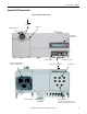
Chapter 1 Product Overview
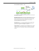
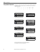
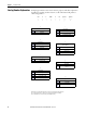
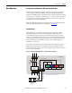
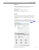
Figure 7 - Control Circuit Wiring Diagram — Multiple External Power Supplies
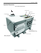
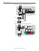
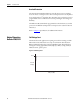
Figure 8 - Control Circuit Wiring Diagram — Internal Power Supply (optional)
Outputs
Inputs
EtherNet
Comms
A3
A1
A2
O
Switched Control Power
Unswitched Control Power
Motor
Control
Motor
Controller
Class 2
External Switched
24VDC Power Supply
Disconnect
24VDC
+
-
L
N
L1 L2
L3
24VDC
+
-
L
N
Class 2
External Unswitched
24VDC Power Supply
* Control power output is determined by disconnect status
*
T1 T2
T3
ArmorStart LT
Outputs
Inputs
EtherNet
Comms
O
Motor
Control
Motor
Controller
Disconnect
Internal Power
Supply
*
* Control power output is determined by disconnect status
T1 T2
T3
ArmorStart LT
*
L2
L3
L1