ESRS – Encoder Signal Reference Simulator (Cat. No.
Important User Information Because of the variety of uses for the products described in this publication, those responsible for the application and use of this control equipment must satisfy themselves that all necessary steps have been taken to assure that each application and use meets all performance and safety requirements, including any applicable laws, regulations, codes and standards.
European Communities (EC) Directive Compliance If this product has the CE mark it is approved for installation within the European Union and EEA regions. It has been designed and tested to meet the following directives.
Table of Contents Preface Using This Manual Read This Manual . . . . . . . . . . . . . . . . . . . Who Should Use this Manual. . . . . . . . . . . Purpose of this Manual . . . . . . . . . . . . . . . Safety Precautions . . . . . . . . . . . . . . . . . . . Contents of this Manual . . . . . . . . . . . . Related Documentation . . . . . . . . . . . . Terminology . . . . . . . . . . . . . . . . . . . . . . . Common Techniques Used in this Manual .
ii Chapter 3 Operation General . . . . . . . . . . . . . . . . . . . . . . . Indicators . . . . . . . . . . . . . . . . . . . . . . Controls . . . . . . . . . . . . . . . . . . . . . . . Line Speed . . . . . . . . . . . . . . . . . . When Set To Unidirectional. . . . . When Set To Bi-directional . . . . . Acceleration. . . . . . . . . . . . . . . . . . Rounding . . . . . . . . . . . . . . . . . . . Line Selection . . . . . . . . . . . . . . . . Inputs and Outputs . . . . . . . . . . . . . . .
Preface Read This Manual Read and understand this instruction manual. It provides the necessary information to let you install, connect, and set up the Encoder Signal Reference Simulator for safe, reliable operation.
Preface P-2 Safety Precautions The following general precautions apply to the Encoder Signal Reference Simulator: ATTENTION ! Electric shock can kill. Make sure the Encoder Signal Reference Simulator is safely installed in accordance with the Installation and Set-up chapters of this manual. Avoid contact with electrical wires and cabling while power is on. Only trained service personnel should open the electrical cabinet. This product contains stored energy devices.
Preface P-3 Contents of this Manual Chapter Title Preface 1 Overview 2 Installation 3 Operation Contents Describes the purpose, background, and scope of this manual. Also specifies the audience for whom this manual is intended. Provides a general description of the Encoder Signal Reference Simulator, its features and mechanical specifications. Provides the steps needed to successfully mount and wire the Encoder Signal Reference Simulator. Provides information on using the ESRS.
Preface P-4 For specific definitions of other terms used in industrial automation, see the Allen-Bradley Industrial Automation Glossary (publication number AG-7.1). Common Techniques Used in this Manual The following conventions are used throughout this manual: • Bulleted lists such as this one provide information, not procedural steps. • Numbered lists provide sequential steps or hierarchical information. • When we refer you to another location, the section name appears in italics.
Preface P-5 Leave the product in its shipping container prior to installation.
Preface P-6 The Rockwell Automation Technical Support numbers are: in Europe: (+44) 1270 580142 in North America (603) 443-5419 On the Web For information about Allen-Bradley, visit the following World Wide Web site: http://www.ab.
Chapter 1 Overview ESRS Description The Encoder Signal Reference Simulator (ESRS) generates a digital speed reference for a motor and encoder feedback combination. In practice the ESRS would be connected to the Master Encoder input of a drive. The ESRS then generates quadrature pulses with selectable index (i.e. marker) which a drive forces its motor/encoder to follow.
1-2 Overview • Digital output indicates phase of quadrature pulse train (i.e. direction of motor rotation). ESRS Front Panel The following illustration shows the placement and labelling of major items on the ESRS front panel. Figure 1.
Overview ESRS Footprint 1-3 The following figure shows the footprint of the ESRS with fixing hole dimensions and drilling details. Figure 1.
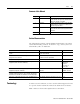
1-4 Overview ESRS Principal Specifications Mechanical Specifications Table 1.A Mechanical Specifications Enclosure Type Steel case with integral mounting feet on rear edge. Enclosure Size English (inch) 11.6 x 13.5 x 1.7 Metric (mm) 295 x 343 x 43 Environmental Specifications Table 1.B Environmental Specifications Operating Power Supply and Fuses Storage Temperature 0 to 60oC Humidity 95% non condensing @ 60oC -40 to 70oC Power Supply Specifications Table 1.
Overview 1-5 Quadrature Output Table 1.D Quadrature Output Number of quadrature outputs provided. One Output format Incremental quadrature with Index pulse. Output data type RS422 TTL Levels. Quadrature output frequency 0 to 275kHz. Quadrature output phase Forward is defined as A phase leading B. Reverse is defined as B phase leading A. Index Pulse Table 1.E Index Pulse Index division ratios. Selectable in the range : 210, 211, 212, 213 pulses.
1-6 Overview Publication 4100-IN505A-EN-P - October 2000
Chapter 2 Installation The ESRS is designed to be mounted in an electrical cabinet via the mounting tabs on its back panel. For all applications, this installation method should be observed. Before powering up your ESRS, make sure it has been configured correctly and that all peripheral equipment has been correctly connected to it. ATTENTION ! Do not apply power to your ESRS when it is part of a control system without first establishing that this will not have any adverse effects.
2-2 Installation Mounting the ESRS The ESRS must be properly grounded to the metal enclosure panel. The following diagram shows how to ground the ESRS to the panel. Figure 2.1 Mounting and Grounding Diagram Enable Input There are several ways in which the Enable Input can be wired. The diagrams on the following pages indicate the various connection options. The following diagram shows how to connect the ESRS to continually enable the device from the internal Enable supply.
Installation 2-3 Figure 2.
2-4 Installation The next diagram shows how to connect the ESRS to enable the device from a source provided by the users equipment. Figure 2.
Installation 2-5 This figure shows how to connect the ESRS to enable the device from its internal Enable supply and control with volt free contacts. Figure 2.
2-6 Installation This diagram shows how to connect the ESRS to enable the device from a source provided by your equipment and control the Enable with volt free contacts. Figure 2.
Installation 2-7 recommended minimum current capacity for the external power supply is 1 Amp. ATTENTION ! The ESRS does not contain reverse supply polarity protection. You must observe polarity when installing the unit. Reverse supply polarity can permanently damage the ESRS. This diagram shows how to connect the ESRS to a power supply adjacent to the ESRS. Figure 2.
2-8 Installation The next diagram shows the ESRS connected to a power supply adjacent to the drive or controller. Figure 2.
Chapter 3 Operation General Your ESRS is fitted with a range of indicators and controls to allow easy configuration and use. This chapter explains the function and operation of these and provides additional technical data where appropriate. Indicators There are two green LED indicators provided on the ESRS front panel: OK and Enable. The OK indicator relates the status of the applied power (either +5V DC or +12V DC) and associated fuse.
3-2 Operation When Set To Bi-directional When Bi-directional Mode is selected, zero speed occurs at the center of rotation. Maximum reverse speed occurs in the MIN position and maximum forward speed occurs in the MAX position. Acceleration The Acceleration control allows the user to set the rate of motor acceleration. It is a 270 degree potentiometer accessible from the front panel of the ESRS. For tamper avoidance, it is screwdriver operated.
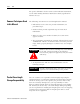
Operation 3-3 EXT – This setting selects a customer supplied line speed input via the EXT LINE SPEED IN input. Inputs and Outputs The following analog and digital inputs and outputs are provided. Line Speed Ref Out The ESRS provides an analog indication of commanded speed after rounding and acceleration have been applied. The analog output range is 0V > Vout > 10V. The output produces a voltage ranging from 0 to +10 V DC as the commanded speed varies from stationary to the selected maximum.
3-4 Operation The Strobe Out is a square wave. Its falling edge is centered between the consecutive rising edges of the Index Pulse. Figure 3.1 ESRS Strobe and Index Pulses Ext Line Speed In This is an analog input requiring a DC voltage within the range of -10V > Vin > +10V. You can set the commanded speed from an analog voltage within this range. Within the selected range, the motor speed is directly proportional to input voltage.
Operation 3-5 The following table shows the Pin number and its signal name. Table 3.A P1 Pin Functions Pin Number 1 2 3 4 5 6 Signal Name Enable Voltage, +15V Enable Voltage, 0V Enable Input Enable Input Direction Input Direction Output, 0V Enable Voltage This provides a current limited supply to power the Enable input. Enable Input This input, which is opto-isolated, allows control of the ESRS via an applied voltage in the range of 5 to 24V DC.
3-6 Operation P2 The P2 connector is a 15 way male high density D connector. It allows you to make connection to the quadrature pulse train and index plus power (+5 and +12V DC). The following table shows the Pin Number and the matching Signal name. Table 3.C P2 Pin Functions Pin Number 1 2 3 4 5 6 7 8 9 10 11 12 13 14 15 Signal Name A+ AB+ BI+ (Z+) Common Common +12V DC +5V DC I- (Z-) Not Used Not Used Not Used +5V DC Shield The A+ and A-, B+ and B-, I+ and I- outputs are RS422 TTL level outputs.
Operation 3-7 Setting the Option Switch You must remove the side panel of the ESRS box to gain access to the DIP switches. ATTENTION ! Removal of the side panel and setting of DIP switches should be performed by authorized personnel only. Proper safety precautions must be followed to reduce the risk of damage to the unit, other equipment, and health of personnel. Set the DIP switches by pressing the appropriate lever to either its ON or OFF position based on the following switch setting values.
3-8 Operation Index Division Ratio Selection Switch 3 and Switch 4 are used to create 4 patterns based on their ON/OFF combinations. The patterns determine the pulse ranges, the pulses per revolution, and the counts per revolution. Table 3.
Index wiring A Enable Input 2-2 Allen-Bradley Support P-5 L C Common Techniques P-4 Connecting external power supply 2-6 External Power Supply Adjacent to Drive/Controller 2-8 External Power Supply Adjacent to Encoder 2-7 Contents of this Manual P-3 Continually 2-3 Controls 3-1 Acceleration 3-2 Line Selection 3-2 Line Speed 3-1 When Set To Bi-directional 3-2 When Set To Unidirectional 3-1 Rounding 3-2 E Enable Input 2-2 Enabled Output Continually Enabled 2-3 ESRS Enabled 2-4 ESRS Enabled via Volt Fre
I-2 Index technical product assistance, P-5 support On the Web P-6 T Terminology P-3 Publication 4100-IN505A-EN-P - October 2000 W Who Should Use this Manual P-1 World Wide Web site P-6
Back Cover Publication 4100-IN505A-EN-P - October 2000 1 Supersedes Publication 4100-5.5 - November 1998 PN 4100-IN505A © 2000 Rockwell International Corporation. Printed in the U.S.A.