
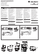
Safety Interlock Switch Instruction Manual

2 x M5 CSK
4 x M5
3 x M20
3 x 1/2" NPT
1112
2122
4344
3334
A1A2
440G-MT
1112
2122
3334
4344
8 9
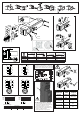
1
4
6
1
3
7
8
2
5
9
10
10
12
6 11
3
7
2
5 4
A1A2
440G-MT QD
1112
2122
4344
3132
A1A2
440G-MT
1112
2122
3132
4344
8 9
1
4
6
1
3
7
8
2
5
9
10
10
12
6 11
3
7
2
5 4
A1A2
440G-MT QD
=
=
3.5mm
11/12
21/22
31/32
43/44
0mm20
=
=
3.5mm
11/12
21/22
33/34
43/44
0mm20
90
2 x M4
0.5 N m
(4.4 lb in)
5mm
440G-A27011
440K-A11112
440G-A27143
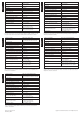
175mm
175mm
60mm
175mm
175mm
60mm
175mm
175mm
60mm
175mm
175mm
60mm
440K-A17116
175mm 175mm
175mm
175mm
C
A
B
D
1.6 N m (14.2 lb in)
45
Max. Ratings
AC DC Applicable Standards
12-Pin M23 63 V, 6A 63 V, 6A IEC 61984:2001
Connectors Ratings
Pin 11 - +24V Input (LED power)
Pin 12 - +24V Diagnostic Output
Pin 11 - +24V Input (LED power)
Pin 12 - +24V Diagnostic Output
FOR NON-QD VERSIONS
Terminal 1 to supply 24VDC to for LED power
Terminal 4 provides 24VDC Diagnostic Output Signal
Terminals 2 & 3 to remain the same as QD version
UNIT MUST BE EXTERNALLY GROUNDED
1. Locate grounding screw hole (both sides).
2. Place customer supplied grounding tab ring
(crimped to ground wire) over hole.
3. Place serrated washer over grounding tab.
4. Secure both to body casting with M4 screw,
torque to 1.4 N•m (12.4 lb•in).
5. Attach ground wire to chassis ground.
Actuator &
sole noid
sta tus
LED
sta tus
Diagnostic
output
sta tus