
User Manual


Publication 700-IN003C-EN-P - October 2009
6 Bulletin 700 Type RTC & RTCR Solid-State Relays
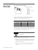
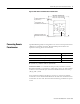
Figure 4 Remote Potentiometer Connections
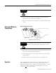
Manual Actuator
Timer can be equipped with a manual actuator (Cat. No. 700–N7) which is
used to energize the initiate circuit (Terminal P) manually using a separate
voltage source, 24V and 120V AC/DC only. It can be easily installed in the
field.
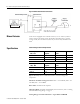
Specifications
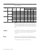
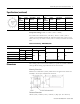
Table 2 Voltage and Power Requirements
Repeat Accuracy: ±1% or ±50 milliseconds at constant voltage and
temperature.
Maximum Available Leakage Currents: 240V – 2.4 m
A RMS, 120V – 2.4
mA RMS, 24V – 10 mA RMS.
Reset Time: 25 millise
conds required.
Operating Mode: O
n-Delay and Off-Delay. For instructions, refer to “Setting
the Mode and Timing Range” on page 3.
Timing Ranges and Switch Positions – Types RTC and RTCR
120V AC or DC
240V AC or DC
AC Voltage 50/60 Hz
+10%, -15%
Total Power
Required
Initiate Terminal P
Power
Coil Code
24V AC 8VA 4VA U24
110-120V AC 9VA 4VA U1
220-240V AC 11VA 5VA U2
DC Voltage
+10%, -20%
Total Power
R
equired
Initiate Terminal P
Power
Coil Code
24V DC 10 W 5 W U24
120V DC 11 W 5 W U1
240V DC 12 W 5 W U2