
Manual


Chapter
1
1
11-1
Coordinate System Offsets
This chapter covers the control of the coordinate systems on the 9/Series
control. G-words in this chapter are among the first programmed because
they define the coordinate systems of the machine in which axis motion is
programmed. This chapter describes:
Information about: On page:
Machine coordinate system 11-1
Preset Workcoordinate systems G54-59.3 11-4
Workcoordinate systems external offset 11-10
Offsettingthe work coordinate systems 11-13
PAL offsets 11-22
A thorough understanding of this group makes programming easier by
allowing full control of the coordinate systems.
The 9/Series control has two types of coordinate systems.
Coordinate System: Description:
work coordinatesystem definedbased onthe coordinatesystem used inthe part
drawing of a part to be cut by themachine. Programs are
usually writtenbased onthe workcoordinate system.
machine coordinate system
(often referred to as the absolute
coordinate system)
unique to the individual machine tool.
The machine coordinate system is the basic coordinate system set for every
machine. It is established after completion of the machine-homing
operation. It cannot be offset or shifted in anyway. Its position is
determined in AMP by your system installer.
Important: Before you can activate any coordinate system, the machine
must be homed. The homing operation refers to the positioning of the axes
to a machine-dependent, fixed position which is called the machine home.
For more on machine homing, refer to page 4-9.
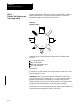
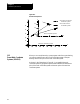
The zero point of the machine coordinate system is referenced from the
machine home point. This is done by assigning a coordinated location to
the machine home point. The home position for each axis can be given
any legal coordinates, such as 15.00, -20.0000, or -2.256.
11.0
Chapter Overview
11.1
Machine (Absolute)
Coordinate System