
Manual
Chapter 11
Coordinate System Offsets
11-11
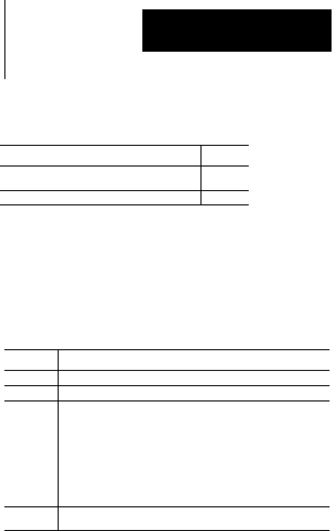
There are 3 methods to change the value of an external offset in the work
coordinate system table. Two methods can be found in the following
sections:
Method: Chapter:
manually alterthe externaloffset valuein thework
coordinate system table
3
alter theparamacro system parameter values5201- 5206 28
The third method, and the one described in this section, alters the external
system table through G10 programming. Changing these values in the
table using any of these methods does not cause axis motion. It does
immediately shift the active coordinate system by the amount entered.
The values entered into the external offset are added to the work coordinate
system zero point values each time a work coordinate system is called.
The format for altering the external offset using G10 is:
G10 L2 P0 O__ X__ Z__;
Where : It :
L2 tells thecontrol that youwant to alter thecoordinate system tables.
P0 designates theexternal offset as theoffset toupdate.
O__ specifies whether thevalue enteredfor the diameter axis is aradius ordiameter
value. (O is non-modal.)
O1=value enteredfor the diameter axis is aradius value.
O2=value enteredfor the diameter axis is adiameter value.
Important: If you program O1 or O2in aG10 code, theG10 codeis not
affectedby apreviously programmedG07 orG08 (radius/diameter
programming). However, if no O-codeis specified, or if theO-code isout of
range (for example, O3), then theG10 codeis affected bya G07/G08.
X_Z_ specifies thelocation of thezero point of thespecified workcoordinate system
relative to machine coordinate system.
When you execute this block, the control immediately shifts the currently
active work coordinate system by the new external offset amount.
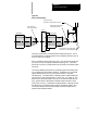
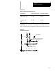
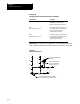
Example 11.4 and Figure 11.9 illustrate how the work coordinate system is
shifted using G10.
11.3.1
Altering External Offset
(G10L2)