
Manual

Chapter
1
3
13-1
Coordinate Control
This chapter describes 9/Series coordinate control.
For information about: See page:
Plane selection G17, G18,G19 13-1
Absolute/Incremental modesG90, G91 13-2
Inch/Metric modesG70, G71 13-4
Radius/Diameter modesG07, G08 13-5
Scaling G14, G14.1 13-7
The 9/Series control has a number of features that operate in specific
planes. For that reason, it is frequently necessary to change the active
plane by using a G17, G18, or G19 code. The G18 plane is always active
at power-up.
Some of the features that are plane-dependant are:
Circular interpolation
Tool tip radius compensation
Many fixed cycle operations
Important: Your system installer determines the axis names and planes
defined by G17, G18, and G19 in AMP. Your system may not have planes
assigned exactly as listed below. Refer to the documentation prepared by
your system installer.
Typical axis names and their corresponding plane assignment are shown
below (this manual assumes this configuration throughout):
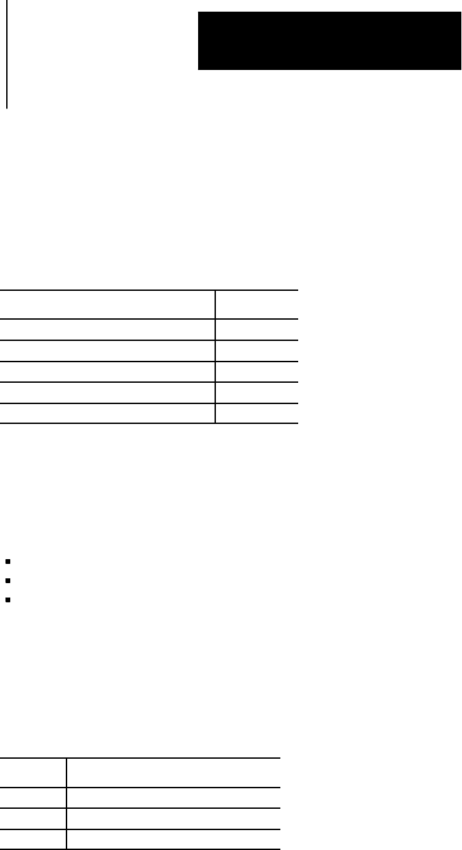
Code: Plane defined by the:
G17 none
G18 Z and X axes(or axes parallelto Zand X)
G19 none
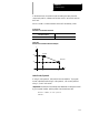
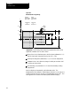
Planes can be altered to accommodate additional axes parallel to the
principle axes by programming those axes in a G17, G18, or G19 block.
See Example 13.1.
13.0
Chapter Overview
13.1
Plane Selection
(G17, G18, G19)