
Manual
Axis Motion
Chapter 14
14-5
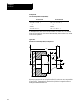
You must establish a plane before the control performs the correct arc.
This should have been done by your system installer, typically assigning
the Z and X axes to the G18 plane. This becomes the default plane that the
control assumes when:
power is turned on
E-Stop is reset
the control is reset
Circular interpolation can be performed in the absolute (G90) or
incremental (G91) mode.
Important: S--Curve Acc/Dec mode is not available with circular
interpolation mode.
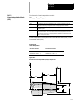
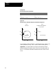
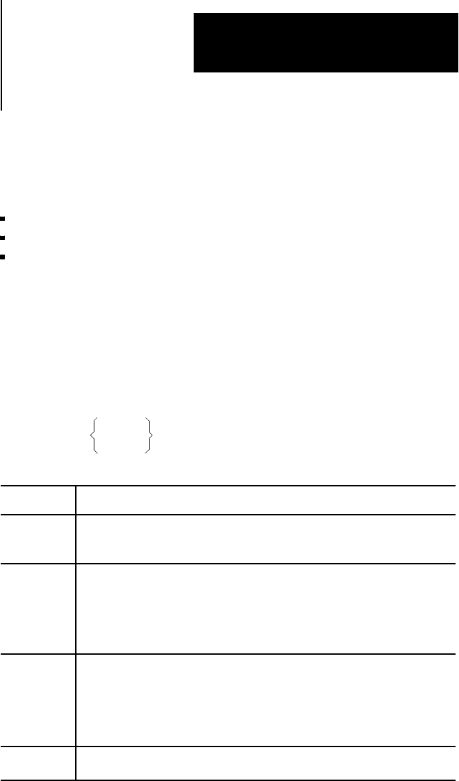
The format for circular interpolation in the ZX plane is:
{G02} X__ Z__ I__ K__ F__ ;
G03 R__
Where : Is :
X, Z In absolute(G90) mode, these arethe workcoordinate valuesof the endpoint.
In incremental (G91) mode, these are the positions of the end point in reference
to the start point.
I, K These determinethe positionof the arccenter. They are theincremental
distance on each axis from thestart point of the arcto thecenter point. These
values arealways incremental, regardlessof the establishedpositioning mode
(absolute or incremental). I is parallelto X axis, andK isparallel toZ axis;, but
his canbe configuredin AMP. These arenot necessary if programming the R
parameter.
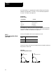
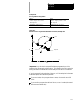
R Rather than defininga center withI, K, the optionexists todefine anarc radius
using R. The signof this entry determinesthe arc centerpoint location. If R is
programmed as a positivevalue, the centerpoint islocated so that an arc less
than 180° is generated. If R isprogrammed asa negativevalue, the centerpoint
is locatedso that anarc greaterthan 180°is generated. Refer to Figure 14.5for
an example.
F Another option isto enter afeedrate tangentialto thearc. If omitted, the control
uses thefeedrate activeprior tothis block.