
Manual
Using QuickPath Plus
Chapter 15
1
5
-
3
If an angle is programmed in a circular QuickPath Plus block, an error is
generated.
If an L-word is programmed in a G13, or G13.1 block an error is
generated.
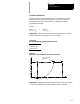
One End Coordinate
Many times part drawings give a programmer only one axis dimension for
a tool path and require that the other axis dimension be calculated by the
angle. This QuickPath Plus feature eliminates the need for this calculation.
This must be a linear block. See section 15.3 for circular block.
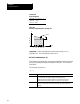
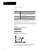
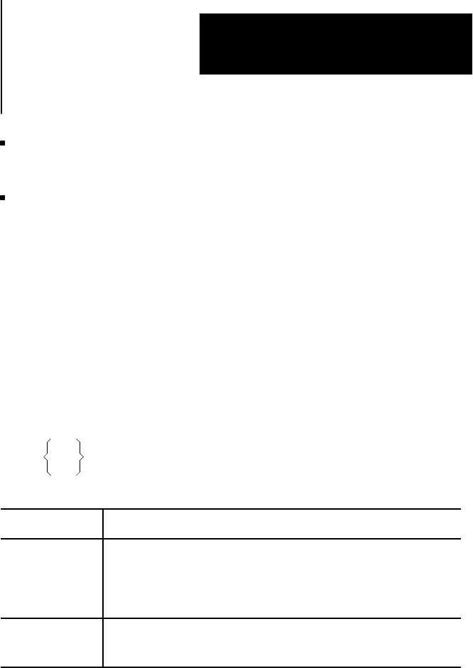
The format for this block is:
,A__ X__ ;
Z__
Where : Is:
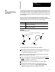
,A Angle This word is used to define the angleof a tool path. This manual
assumes that the,A-word isused. The angle is a positive value when
measured counterclockwise from thefirst axis definingthe currentlyactive
plane and a negative valuewhen measuredclockwise. The angleis in
units of degrees.
X,Z End Point This word is used toprogram oneof the coordinatesof the endpoint of a
linear path. The controlcalculates theother end point automatically. This
can be any axisword that isin the current plane.
Only one axes word from the current plane can be programmed in this
block. Any axis word that is not in the current plane is executed as a
normal linear move to that coordinate and combined with the QuickPath
Plus generated tool path. If both axis words from the current plane are
entered in the block, the angle is ignored and the control moves to the
coordinate position programmed with the axis words. All examples in this
section assume that the ZX plane is active.
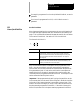
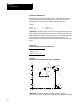
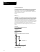
Important: If the programmed tool path is going to be parallel to an axis
in the current plane, the axis word for the end point in the block should be
for the axis in the current plane that is not parallel to the tool path. This
means if the value of the angle (,A-word) is 0° or 180°, the second axis in
the plane must be programmed in the block. If the value of the angle is
90° or 270°, the first axis in the plane must be programmed in the block.
15.2
Linear QuickPath Plus