
Manual

Chapter
1
6
16-1
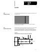
Chamfering and Corner Radius
During cornering, the 9/Series control has the option of performing either a
chamfer (a linear transition between the blocks) or a corner radius (an arc
transition between blocks).
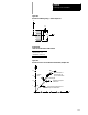
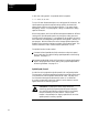
,C Chamfer size This word isused to define a chamfer lengththat connects two
intersecting tool paths. This worddetermines thedistance that
the chamfer begins and ends from thetool paths intersection.
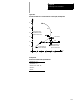
,R Corner radius This wordis usedto definethe radiusof an arcthat is tangent
to two intersecting tool paths.
This chapter describes chamfering and corner radius in detail. Major
topics include:
Topic: On page:
Chamfering 16-2
Corner radius 16-4
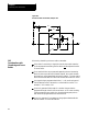
Both the chamfer and the corner radius features are generated between two
motion blocks that must be programmed in the same plane. The motion
block with the corner chamfering (,C) or the corner radius (,R) word is
defined as the first cornering block. The next motion block in the
cornering plane is defined as the second block.
If more than one ,C- or ,R-word is programmed in the same block, only the
right-most word is used; others are ignored. The second block can also
have a corner chamfering or corner rounding word in it. If it does, the
second block is also used as the first block of the next corner chamfering
or corner rounding.
CAUTION: If you make a programming error of some type is
made in the block defining the second tool path in the chamfer
or radius blocks, the control is not able to cut the correct
chamfer or radius. Instead, the first block is executed to its
programmed endpoint. This can cause damage to the part or
cutting tool.
16.0
Chapter Overview