
Manual

Spindles
Chapter 17
17-13
Example 17.1
9/290 Control with 3 Spindles Configured in AMP
N0001 M05
Spindle 1 stop
N0002 M05.2 M05.3
Spindles 2& 3stop
N0003 M03 M04.2 S150
Spindle 1 clockwise 150 rpm
Spindle 2 counterclockwise 150 rpm
N0004 M03.2 M03.3 S10
Spindle 2 clockwise 10 rpm
Spindle 3 counterclockwise 10 rpm
Important: On the 9/260 and 9/290 controls, if the auxiliary spindle
directional M-codes are programmed but the auxiliary spindles have not
been configured as active through AMP, these errors are given as decode
errors on any blocks that have directional M-codes of the associated
spindle programmed:
“SPINDLE 2 NOT CONFIGURED” and/or
“SPINDLE 3 NOT CONFIGURED”
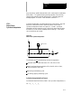
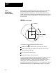
The Virtual C Axis feature allows the control to interpolate a rotary axis
(typically the lathe spindle) with the machine axes. This allows for
circular machining along the circumference or across the face of a
workpiece while it is rotated, as shown in Figure 17.3 and Figure 17.5.
If the spindle is used as the virtual C axis, it may require that an alternate
motor and/or higher precision feedback device be used. The alternate
motor would be configured as a closed-loop rotary axis. Refer to the
documentation provided by your system installer.
This description assumes that the lathe spindle has been configured in
AMP to be used as the virtual C axis.
Werefer to this axis: As:
the virtual C axis C
the axis along thespindle centerline (also called the park axis) Z
the axis perpendicular to the spindlecenter line (alsocalled thefeed axis) X
Refer to the literature provided by your system installer for the axis names
used by your machine.
17.5
Virtual C Axis