
Manual
Tool Control Functions
Chapter 20
2
0
-
6
You can enter data in the tool offset tables by programming the correct
G10 command. This section describes the use of the G10 commands for
the lathe tool offset table.
Important: Only the value in the offset table value changes when a G10
code modifies a tool offset table value. If the changed offset value is
currently being used by the control, the active offset value is not changed
until it is called again from the offset table using a T-word.
When the control is in incremental mode (G91), any values entered in an
offset table using the G10 command are added to the currently existing
offset values. When the control is in absolute mode (G90), any values
entered in an offset table using the G10 command replace the currently
existing offset values.
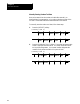
This is a representation of the basic format for modifying the offset tables.
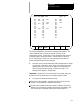
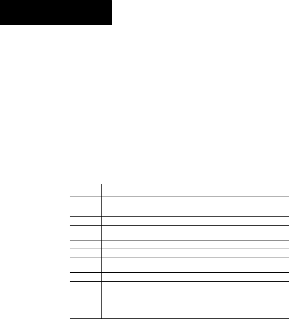
G10 L(10-11)P__ X__ Z__ R__ Q__ T__ O__
Where : Is :
L(10-11)
Designates whichoffset tableis beingmodified.
L10-Modifies thetool geometry table.
L11-Modifies thetool wear table.
P
The tool offset number that ishaving its values changedis specifiedfollowing theP address.
X
The value to add to(in G91mode) or replace (inG90 mode)the toollength offset for theX axis.
This valuemay bea diameteror radius valueas determinedwith theO-word.
Z
The value to add to(in G91mode) or replace (inG90 mode)the toollength offset for theZ axis.
R
The value to add to(in G91mode) or replace (inG90 mode)the tooltip radius amount.
Q
The value to add toor replace thetool orientationamount
(valid only when settingdata forthe geometry table).
T
A T-word that correspondsto thetool number that isbeing changed.
O
Determines if thevalue beingentered intothe offset table is a radiusor diameter value. This
only applieswhen settingdata forthe controls diameter axis (typicallythe axis perpendicular to
the spindle). If no O-wordis programmed the control usesthe current radius/diameter mode
active on the control.
O1-indicates aradius value
O2-indicates adiameter value
Important: Any axis word may be entered here along with/or without the
X- or Z-words. The lathe offset table allows the entry of offsets for up to
four different axis, tool radius, and tool orientation for each offset number.
Any values not specified in the G10 block remain unchanged.
20.2
Entering Tool Offset Data
Using (G10L10, G10L11)