
Manual

Chapter
2
3
23-1
Grooving/Cutoff Cycles
These two cycles are provided to perform grooving or cutoff operations:
G76 Face Grooving Cycle
G77 O.D. & I.D. Grooving Cycle
This chapter reviews the following major topics:
Topic: On page:
Face grooving cycle 23-3
O.D. & I.D. cycle 23-6
Important: Descriptions in this chapter are written assuming the control is
in the G18 plane and that plane has been defined as the ZX plane. If your
system has a different plane active, operation of these features is different.
Parameters are defined here assuming Z is the first axis in the plane, and X
is the second axis in the plane. If, for example, the XZ plane is the
currently active plane, descriptions in this document should be interpreted
accordingly (i.e., Z axis description applies for X axis and X axis
description applies to Z axis. See your system installer’s documentation
for details on the plane definitions on your system.
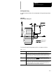
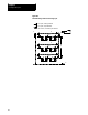
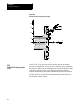
Figure 23.1 shows the tool path during a typical G76 Face Grooving Cycle.
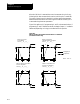
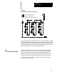
Figure 23.2 shows the tool path during a typical G77 O.D. Grooving
Cycle.
Multiple grooves at a programmed distance and depth are cut by a single
G76 or G77 block.
23.0
Chapter Overview