
Manual

Chapter
2
6
26-1
Drilling Cycles
This chapter covers the G-word data blocks in the drilling cycle group.
The operations of the drilling cycles are explained on these pages:
Topic: Page:
Drilling cycles 26-1
Positioning and Hole Machining Axes 26-4
Parameters 26-7
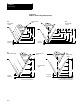
Drilling Cycle Operations 26-8
Altering Drilling Cycle Operating Parameters 26-38
Fixed Drilling Cycle Examples 26-40
WARNING: The cycles described in this chapter can be used
with live tooling. This application however requires proper
PAL control of the spindle, especially in cycles that perform
spindle orients or change the spindle rotation direction. Failure
to do this can result in injury to personal or damage to
equipment.
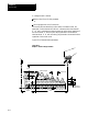
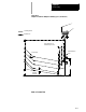
Drilling cycles, sometimes referred to as canned cycles or auto cycles,
repeat a series of basic machining operations, such as boring, drilling, or
tapping. These operations, designated by a single-block command, usually
consist of a fixed series of steps that are dependent on the type of
machining application.
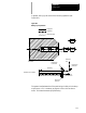
For this chapter, as well as this manual, assume that the Z axis is the hole
machining axis. The hole machining axis is established by the system
installer.
If you are using a dual-processing system, refer to chapter 30 for more
details about drilling fixed cycles for your system.
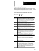
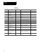
The control provides the drilling cycles shown in Table 26.A.
26.0
Chapter Overview
26.1
Drilling Cycles