
Manual

Drilling Cycles
Chapter 26
26-4
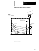
This section assumes that the programmer can determine the hole
machining axis using the plane select G-codes (G17, G18, G19). Refer to
the system installer’s documentation to make sure that a specific axis has
not been selected in AMP to be the hole machining axis.
G-codes G17, G18, or G19 determine the plane, the hole machining axis,
and the positioning axes. The two axes that define the selected plane are
used as positioning axes. The axis perpendicular to the plane is the hole
machining axis.
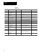
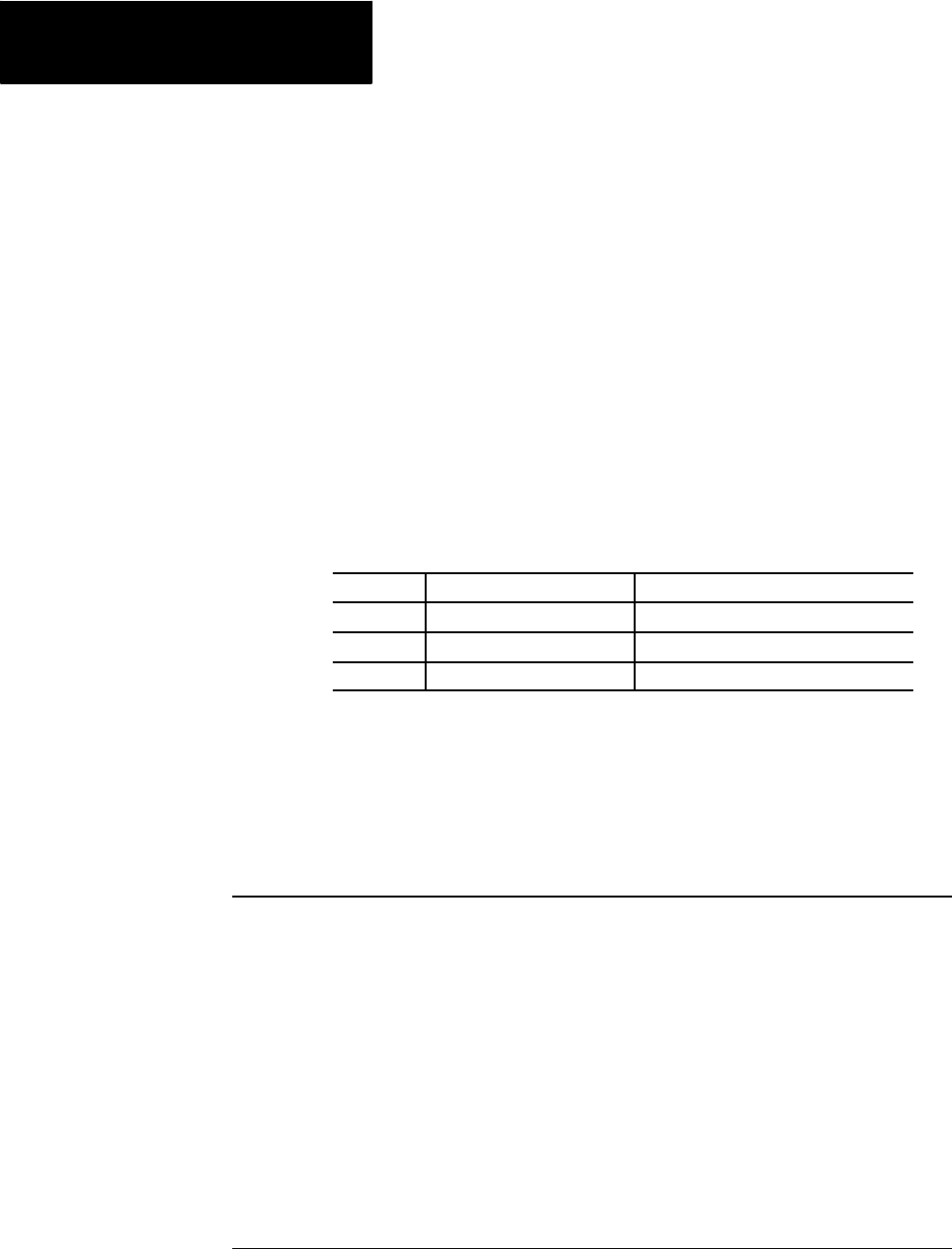
Table 26.B assumes a specific plane definition. Refer to the system
installer’s documentation for the plane definitions on your system.
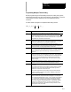
Table 26.B
Plane Selection vs Machining Axis
Plane Hole Machining Axis Positioning Axes
XU (G17)
Z axis or its parallelaxis X andU axesor their parallel axes
ZX (G18)
U axisor its parallelaxis Z andX axesor their parallel axes
UZ (G19)
X axisor its parallelaxis U andZ axesor their parallel axes
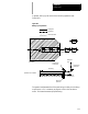
Example 27.1 shows you how to change the hole machining axis to a
parallel axis. Prior to changing the hole machining axis, a G80 should be
executed to cancel any active milling mode.
Example 27.1
Altering the Machining Axis to a Parallel Axis
Program Block Comment
The W axis is parallel to the Z axis.
G17;
XU plane active
G81X ___ U ___ ;
Drilling cycle, Z is the hole
machining axis
.
.
G80;
Cancel drilling fixed cycle
mode
G81X ___ U ___ W ___;
Drilling cycle, W is the hole
machining axis
.
.
The plane selection codes (G17, G18, and G19) can be included in the
drilling fixed cycle block, or can be programmed in a previous block.
26.2
Positioning and Hole
Machining Axes