
Manual

Drilling Cycles
Chapter 26
26-7
This section provides a detailed explanation of each parameter you can
program for the drilling cycles. Some parameters are not valid with all
cycles; see the specific description of each cycle. To alter drilling cycle
operation parameters, see section 26.5.
These drilling cycle parameters are described below:
X__Y__Z__R__ I__J__K__ P__F__L__Q__D__S__;
Where : Is:
X
specifies the location of thehole position in the selected plane. In theabsolute mode
(G90), program thehole positionusing thecoordinate valuesin theactive coordinate
system. In incremental mode(G91), program thehole positionusing thedistance from the
current tool positionto therequired holeposition. This parameter is affected by radiusor
diameter programmingmodes.
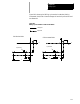
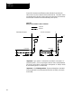
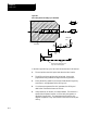
Z
defines the hole bottom. In absolutemode (G90), program thehole bottom levelusing the
coordinate value in the activecoordinate system. In theincremental mode(G91), program
the distance from theR point level tothe holebottom level.
R
defines the R point level. In theabsolute mode(G90), program the Rpoint level asa
coordinate value in the activecoordinate system. In theincremental mode(G91), program
the R point level bythe distancefrom the initialpoint level tothe Rpoint level.
I, J, K
define the shift amount for G86.1and G87.
P
defines the dwell period at holebottom. P programsthe dwellin thesame wayas G04:
seconds if infeedrate mode(G94), spindle revolutionsif in revolution mode (G95). (The
allowable dwell time range in secondsis 0.001-99999.99. The allowable dwell rangein
revolutions isalso 0.001-99999.999.) The P-word does not applyin all drilling cycles.
F
defines the cutting feedrate. If this parameter isnot specified, the controluses the
currently activefeedrate forthe cuttingfeedrate. For G84.2 andG84.3, F =tap threadlead
in inches/mm per revolution.
L
defines the number of times thedrilling cycle is repeated. The maximum numberof
repeats is9999.
· In absolute mode, the control drillsin thesame location the number of times specifiedby
the L-word.
· In incremental mode, theL-word drillsthe numberof holes specifiedby theL-word at
equally spacedpositions, determined byaxis positioningparameters Xand Y.
· If an L0 is programmed, the controldecodes themilling cycleinformation, but does not
execute the drilling cycle. If no L-wordis programmed, thecontrol defaults toL1.
Q
In G83, Q defines the infeedamount for eachmove madein thehole.
In G86.1 and G87, Q defines the shiftamount (asdo I, J, andK).
In G84.2 and G84.3, Q defines the angleat which toorient thespindle beforestarting the
tap. If you don’t program theQ-word, the spindleis not orientedbefore thetap begins. This
means that thehole isnot retappable unlessa Q-word is programmedin thecycle block.
The spindle is brought toa stopprior tothe initiationof the tappingphase evenif Q isnot
programmed; this happensafter the move tothe R-plane.
D
defines the return spindle speedso that, if youwant, the tap-out move can be performed
faster or slower thanthe tap-in. Tool selectionby D-wordis not possiblewhile inthe
solid-tapping mode.
S
defines spindle speed in rpm.
26.3
Parameters