
Manual

Drilling Cycles
Chapter 26
26-13
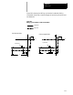
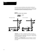
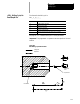
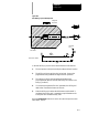
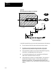
In the G83 drilling cycle, the control moves the axes in this manner:
1. The tool rapids to initial point level above the hole location.
2. The drilling tool then rapids to the R point level, slows to the
programmed cutting feedrate and begins the deep hole drilling
operation.
3. During the drilling operation, the control infeeds the drilling tool by
an amount Q, as programmed in the G83 block.
4. The drilling tool retracts at a rapid feedrate to the R point level.
5. The control feeds the drilling tool at rapid feedrate to a distance d
above the level drilled in the previous infeed. The amount d is
specified by the system installer, or can be set by the operator as
described in section 27.5. This intermittent feed simplifies chip
disposal and permits a very small retraction amount to be set in deep
hole drilling.
6. The drilling tool slows to the cutting feedrate again and infeeds an
amount Q + d.
7. The cutting tool is then retracted at a rapid feedrate to the initial point
level as determined by G98.
When the single block function is active, the control stops axis motion
after steps 1, 2 and 7.
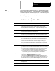
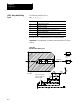
The format for the G83.1 cycle is:
G83.1X__Z__R__Q__P__F__L__;
Where : Is :
X specifies the locationof the holeposition in the selected plane.
Z defines the holebottom.
R defines the Rpoint level.
Q defines the infeedamount for eachstep intothe hole.
P defines the dwellperiod at holebottom.
F defines the cuttingfeedrate.
L defines the numberof times thedrilling cycleis repeated.
See page 26-7 for a detailed description of these parameters.
Important: The programmer or operator must start spindle or live tool
rotation.
(G83.1): Deep Hole Peck
Drilling Cycle with Dwell