
Manual

Drilling Cycles
Chapter 26
26-34
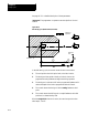
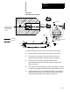
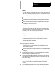
6. After reaching the Z depth, the spindle or live tool rotation stops so
that the control can re-orient the back boring tool to the position
specified in AMP.
The back boring tool is shifted a third time, in the same manner as in
step 2, so that it is again “off-center” and can be removed through the
existing hole.
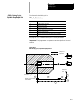
7. The back boring tool moves at a rapid feedrate to the initial point
level regardless of whether G98 or G99 is active.
8. The back boring tool is shifted a fourth time, in the same manner as
in step 2, returning to the initial X coordinates of the hole location.
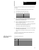
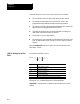
The format for the G88 cycle is:
G88X__Z__R__P__F__L__;
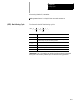
Where : Is :
X specifies location of thehole.
Z defines the holebottom.
R defines the Rpoint level.
P defines the dwellperiod at thehole bottom.
F defines the cuttingfeedrate.
L defines the numberof times thedrilling cycleis repeated.
See page 26-7 for a detailed description of these parameters.
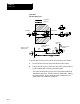
Important: The programmer or operator must start spindle or live tool
rotation.
(G88): Boring Cycle,
Spindle Stop/Manual Out