
Manual
Chapter 30
Using a 9/Series Dual--Processing System
3
0
-
1
3
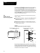
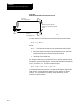
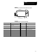
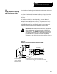
Shared spindle configurations are for those dual-processing systems that
have one spindle that must be controlled by both processes. See
Figure 30.4. As a general rule for this type of machine, spindle control is
given to the process currently requesting spindle control.
WARNING: It is the programmer’s responsibility to watch for
conflicting overlap of spindle control between the two
processes. For example, one process should not request
clockwise spindle rotation while the other process requires
counterclockwise rotation. Prevention of overlapping spindle
control can be accomplished through synchronization M-codes.
See page 30-7.
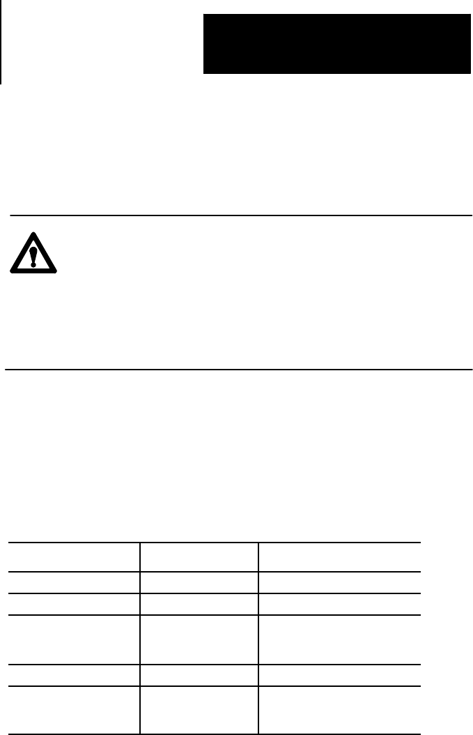
Simple Spindle Speed and Direction
The process that requests a change in spindle speed or direction gets
control of the shared spindle. This can cause problems when both
processes are performing operations that require control over the spindle.
For example, consider the following program segments.
Process 1 Process 2 Shared Spindle Operation
N51 G97 S200 M04; 200 RPM, counterclockwise
N21 G97 S500 M03; 500 RPM, clockwise
N52 G01 X10 Z5; 500 RPM, clockwise
(cutting with process 2direction
and RPM)
N22 G01 X12 Z--1 500 RPM, clockwise
N53 X12 Z3 S275; 275 RPM, counterclockwise
(cutting with process 1direction
and RPM)
30.4.1
Shared Spindle
Configurations