
Manual
Chapter 30
Using a 9/Series Dual--Processing System
3
0
-
2
8
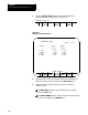
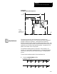
This is a representation of the basic format for modifying the tables.
G10 L{ }P__ X___ Z___ I___ K___;
5
6
Where : Is :
L(5-6)
The definition of which area inthe tableis being modified.
L5 - Modifies the Area1 values
L6 - Modifies the Area2 values
P
The boundary number of the interference boundarythat is having its values changedis
specified following the P address.
X
The value to add to(in G91mode) or replace (inG90 mode)the positiveX axisvalue. This
value is always aradius value.
Z
The value to add to(in G91mode) or replace (inG90 mode)the positiveZ axis value.
I
The value to add to(in G91mode) or replace (inG90 mode)the negativeX axisvalue. This
value is always aradius value. I is theintegrand wordof the Xaxis.
K
The value to add to(in G91mode) or replace (inG90 mode)the negativeZ axis value. K isthe
integrand word of the Z axis.
Programming this G10 code can change only the table values for the
process that has the G10 part program currently active. You must run
separate G10 programs in each process to set up each area.
Important: G10 blocks cannot be programmed when TTRC is active.
Example 30.8
Using G10 to Change the Interference Boundaries
N1 G90 G70;
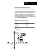
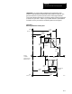
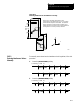
N2 G10 L5 P1 Z19.5 K13 X19 I15; Boundary number1 area1 isdefined.
N3 G10 L6 P1 Z23 K19.5 X18.5 I11; Boundary number 1area 2is defined.