
User guide

Contrôleur de température
Cartes optionnelles 900-TC8
Temperaturregler
Zusatzplatinen 900-TC8
Temperature Controller
900-TC8 Option Boards
900-TC8EIM
Event Input
900-TC8COM (B)
RS-485 Communications
900-TC8232 (B)
RS-232 Communications
900-TC8EIM
Ereigniseingang
900-TC8COM (B)
RS-485-Kommunikation
900-TC8232 (B)
RS-232-Kommunikation
900-TC8EIM
Entrée d'événement
900-TC8COM (B)
Communications RS-485
900-TC8232 (B)
Communications RS-232
Inhalt der Verpackung
Technische Daten
Einbau der Platine
In der Verpackung sind die folgenden Komponenten enthalten:
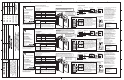
Verdrahtung der 900-TC8232
Allen-Bradley Company, LLC
Industrial Components Business
1201 South Second Street
Milwaukee, WI 53204-2496 USA
Telefon: +1.440.646.5800
Rockwell Automation
CH-5001 Aarau, Schweiz
FAX ++41.62.837.2202
Kontakteingang
EIN: max. 1 kOhm, AUS: mind. 100 kOhm
900-TC8EIM Schlie§erkontakteingang
Spannungsabfall im EIN-Zustand: max. 1,5 V
(elektronisches Relais)
Leckstrom im AUS-Zustand: max. 0,1 mA
Schnittstelle: RS-232, RS-485
900-TC8232 Kommunikation: Halbduplex
900-TC8COM Synchronisation: Start/Stopp (asynchron)
Baudrate: 1,2 / 2,4 / 4,8 / 9,6 / 19,2 /
38,4 kBit/s
1
3
2
Einsatz der Platinen:
900:TC8EIM: Ereigniseingang
900-TC8232: RS-232
900-TC8COM: RS-485
Um eine durch elektrostatische Entladung verursachte
Beschädigung der Platine zu vermeiden, müssen Sie vor
der Installation sicherstellen, dass Sie ordnungsgemäß
geerdet sind. Beachten Sie Folgendes:
RS-485
9 (-)
12 (+)
FG
12
11
A(-)
B(+)
RS-485
12
11
A(-)
B(+)
900-TC8 (Nr. 1)
900-TC8... (Nr. 31)
Abschlusswiderstand
(120 Ohm, 0,5 W)
RS-232-Schnittstellenwandler
Abgeschirmtes
Kabel
900-TC8
Abgeschirmtes
Kabel
900-TC8
11
12
13
RS-232
SD
RD
SG
Ereigniseingang 1 und 2
EV1
EV2
COM
13
12
11
+
+
-
Verdrahtung der
900-TC8EIM
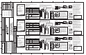
Verdrahtung der 900-TC8COM
900-CONV...
900-TC8
Nr.
FG 1
SD 3
RD 2
RS 7
CS 8
DR 6
SG 5
ER 4
RS-232: 9-polig
Host-Computer (PC)
EV1
EV2
EV1
EV2
COM
13
12
11
+
+
-
Für
Anschluss
an PC
Eine detaillierte Bedienungsanleitung
finden Sie im Benutzerhandbuch des
900-TC8 online unter der Adresse:
http://www.ab.com/manuals/.
For detailed operating instructions,
please refer to the 900-TC8 User's
Manual. It can be found online at:
http://www.ab.com/manuals/
* An die Ereigniseingangsklemmen darf
keine Spannung angelegt werden.
Contents of option board box
Specifications
- Option Board
Installing Board
Make sure the box contains the following items:
Wiring 900-TC8232
Name
900-TC8COM
900-TC8232
900-TC8EIM
Communication (RS-485)
Communication (RS-232)
Event input
Model Function
Communications
Communications
Event input
Allen-Bradley Company, LLC
Industrial Components Business
1201 South Second Street
Milwaukee, WI 53204-2496 USA
Phone 440 646 5800
Rockwell Automation
CH-5001 Aarau, Switzerland
FAX ++41.62.837.2202
Contact input ON: 1k Ohm max.,OFF: 100k Ohm min.
900-TC8EIM
No-contact input ON state voltage drop 1.5 V max.
(SSR) OFF state leakage current 0.1 mA max.
Interface: RS-232, RS-485
900-TC8232 Communications method: Half duplex
900-TC8COM Synchronization method: Start-stop (asynchronous)
Baud rate: 1.2 / 2.4 / 4.8 / 9.6 / 19.2 / 38.4 kbps
1
3
2
Location for boards:
900:TC8EIM: Event input
900-TC8232: RS-232
900-TC8COM: RS-485
To prevent electrostatic damage to the board,
make sure you are properly grounded before
installing it. Follow steps below.
RS-485
9 (Ð)
12 (+)
FG
12
11
A(Ð)
B(+)
RS-485
12
11
A(-)
B(+)
900-TC8 (No. 1)
900-TC8... (No. 31)
Terminator
(120 Ohm 1/2W)
RS-232 Interface Converter
Shielded cable
900-TC8
Shielded cable
900-TC8
11
12
13
RS-232
SD
RD
SG
Event input 1 and 2
EV1
EV2
COM
13
12
11
+
+
-
Wiring 900-TC8EIM
Wiring 900-TC8COM
900-CONV...
900-TC8
No.
FG 1
SD 3
RD 2
RS 7
CS 8
DR 6
SG 5
ER 4
RS-232: 9 Pin
Host computer (PC)
EV1
EV2
EV1
EV2
COM
13
12
11
+
+
-
Connect
to PC
*Do not apply voltage to event input
terminals.
Contenus de l'emballage de l'option
CaractŽristiques
Installation de la carte
Vérifiez que la boîte contient les articles suivants :
Câblage de la carte 900-TC8232
Allen-Bradley Company, LLC
Industrial Components Business
1201 South Second Street
Milwaukee, WI 53204-2496 USA
Tél. : ++ 1.440.646.5800
Rockwell Automation
CH-5001 Aarau, Suisse
Fax : ++41.62.837.2202
Contact d'entrée
ON : 1 kOhms maxi., OFF : 100 kOhms mini.
900-TC8EIM Pas de contact d'entrée Etat ON, chute de tension maxi. 1,5 V
(relais statique)
Etat OFF, courant de fuite maxi. 0,1 mA.
Interface : RS-232, RS-485
900-TC8232 Méthode de communication : Half duplex
900-TC8COM Méthode de synchronisation : Marche-Arrêt (asynchrone)
Vitesse en Baud : 1,2 / 2,4 / 4,8 / 9,6 / 19,2
/ 38,4 kBauds
1
3
2
Emplacement des cartes :
900:TC8EIM : Entrée événement
900-TC8232 : RS-232
900-TC8COM : RS-485
Pour éviter les détériorations électrostatiques,
vérifiez que vous êtes correctement mis à la terre
avant de l'installer. Suivez les étapes ci-dessous.
RS-485
9 (-)
12 (+)
FG
12
11
A(-)
B(+)
RS-485
12
11
A(-)
B(+)
900-TC8 (N° 1)
900-TC8... (N° 31)
Terminateur
(120 Ohms 1/2 W)
Convertisseur d'interface RS-232
Câble blindé
900-TC8
Câble blindé
900-TC8
11
12
13
RS-232
SD
RD
SG
Entrée événement 1 et 2
EV1
EV2
COM
13
12
11
+
+
-
Câblage de la carte
900-TC8EIM
Câblage de la carte 900-TC8COM
900-CONV...
900-TC8
N°
FG 1
SD 3
RD 2
RS 7
CS 8
DR 6
SG 5
ER 4
RS-232 : 9 broches
Ordinateur hôte (PC)
EV1
EV2
EV1
EV2
COM
13
12
11
+
+
-
Connectez
au PC
* N'appliquez pas de tension sur les
bornes d'entrée d'événement.
Pour connaître le détail des instructions
de fonctionnement, veuillez consulter le
manuel utilisateur 900-TC8. Il peut être
trouvé en ligne sur le site :
http://www.ab.com/manuals/
- Instruction Manual
- Terminal Label
Bezeichnung
900-TC8COM
900-TC8232
900-TC8EIM
Kommunikation (RS-485)
Kommunikation (RS-232)
Ereigniseingang
Ausführung Funktion
Kommunikation
Kommunikation
Ereigniseingang
- Anleitungshandbuch
- Klemmenetikett
- Zusatzplatine
Nom
900-TC8COM
900-TC8232
900-TC8EIM
Communication (RS-485)
Communication (RS-232)
Entrée événement
Modèle Fonction
Communications
Communications
Entrée événement
- Manuel d'instructions
- Etiquette de bornier
- Carte optionnelle
*Only one controller per host PC
*Cable length should not
exceed 15 meters (50 ft).
* Use shielded twisted pair
leads (AWG24 to AWG14 [equal to
cross sectional areas of 0.205 to
2.081mm
2]
) for the cables.
* A 10 ft pre-made cable with 9 pin
D-shell connector and open leads
is available (900-CP1X).
* Jeweils nur ein Regler je Host-PC
* Die Länge des Kabels sollte
höchstens 15 Meter betragen.
* Für die Kabel sind abgeschirmte
Twisted-Pair-Leiter (AWG 24 bis
AWG 14 [entspricht Querschnitt von
0,205 bis 2, 081 mm2]) erforderlich.
* Ein 3 Meter langes Kabel mit 9
poligem D-Anschluss-Stecker und
offenen Leitern ist lieferbar
(900-CP1X).
* Seulement un contrôleur par PC
hôte.
* La longueur de câble ne doit pas
dépasser 15 mêtres (50 pieds).
* Pour les câbles, utilisez des paires
torsadées blindées (AWG24 à
AWG14 [égal à des sections de
0,205 à 2,081 mm2]).
* Un câble préfabriqué de 3 mêtres
équipé d'un connecteur D-shell 9
broches et de conducteurs nus est
disponible (900-CP1X).
* The RS-485 total cable length should
not exceed 500 meters.
* Use shielded twisted pair leads
(AWG24 to AWG14 [equal to cross
sectional areas of 0.205 to 2.081mm
2
])
* Attach terminators to the controllers at
both ends of a series of controllers
connected in an open configuration.
For example in the configuration shown,
connect a terminator to the RS232
Interface Converter and connect a
terminator to device number 31.
*Up to 32 controllers including the host
computer can be connected.
* Die gesamte RS-485-Kabellänge sollte
maximal 500 Meter betragen.
* Für die Kabel sind abgeschirmte
Twisted-Pair-Leiter ((AWG 24 bis AWG
14 [entspricht Querschnitt von 0,205 bis
2, 081 mm2]) erforderlich.
* Bei einer offenen Konfiguration müssen
die Abschlusswiderstände an den
Reglern an beiden Enden einer Reihe
von Reglern angebracht werden.
Beispielsweise wird in der abgebildeten
Konfiguration jeweils ein
Abschlusswiderstand an den RS232-
Schnittstellenwandler und an Gerät Nr.
31 angeschlossen.
* Es kännen bis zu 32 Regler,
einschließlich Host-Computer,
angeschlossen werden.
* La longueur totale du câble RS-485 ne
doit pas dépasser 500 mêtres.
* Pour les câbles, utilisez des paires
torsadées blindées (AWG24 à AWG14
[égal à des sections de 0,205 à 2,081
mm2]).
* Attachez les terminateurs sur les
contrôleurs situés aux extrémités d'une
série de contrôleurs branchés en une
configuration ouverte.Par exemple, dans
la configuration illustrée, branchez un
terminateur sur le convertisseur
d'interface RS232 et un autre sur le
dispositif numéro 31.
* Jusqu'à 32 contrôleurs, y compris
l'ordinateur, peuvent être connectés.
41063-070-01 (3)
Printed In China
41063-070-01 (3)
Printed In China
41063-070-01 (3)
Printed in China
1617253-1A
RA1
728-01-2
REVISION
AUTHORIZATION
DIMENSIONS APPLY BEFORE
SURFACE TREATMENT
(DIMENSIONS IN INCHES)
TOLERANCES UNLESS
OTHERWISE SPECIFIED
REFERENCE
SHEET OF
DWG.
B
DR.
CHKD.
APPD.
DATE
DATE
DATE
±
±
±
ANGLES:
.XXX:
.XX:
THIS DRAWING IS THE PROPERTY OF
THE ALLEN-BRADLEY CO. INC.
AND MAY NOT BE COPIED, USED OR
DISCLOSED FOR ANY PURPOSE EXCEPT
AS AUTHORIZED IN WRITING BY
THE ALLEN-BRADLEY CO. INC.
LOCATION : MILWAUKEE, WISCONSIN U.S.A.
SIZE
G. Ushakow
M. Jutz
D. Schneider
7-12-06
7-12-06
7-12-06
1
2
41063-070
E-DOC
PRODUCT INSTRUCTION SHEET
DOCUMENT FOR 900-TC8
TEMPERATURE CONTROLLER
OPTION BOARDS
1
1014782
2
1023782
3
N/A
N/A
N/A
41063