
User manual


Chapter
5
Configuring a Scanner to Communicate
with the Adapter
Chapter Objectives
Chapter 5 provides instructions for configuring your scanner to
communicate with either the 1203-GU6 module or 1336-GM6 board.
This allows the product connected to the adapter to be an active node
on the DeviceNet network. In this chapter, you will read about the
following:
• Equipment and software needed for the configuration.
• Configuring a PLC or SLC scanner to communicate with the
adapter.
Required Equipment and Software
Before configuring the scanner, your PC must be:
• Running RSNetWorx for DeviceNet. Refer to
http://www.software.rockwell.com for more information.
• Connected to and communicating with the DeviceNet network
using a DeviceNet interface such as a 1784-PCD card or a
1770-KFD adapter.
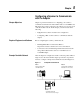
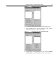
Example DeviceNet Network
After the adapter is configured, it and the connected product will be a
single node on the network. This chapter provides the steps that are
needed to configure a simple network like the network in Figure 5.1.
Figure 5.1 Example DeviceNet Network
JOG
ESC SEL
Node 0
SLC 500 Controller with
1747-SDN Scanner
Node 62
Computer with 1770-KFD and
RSNetWorx for DeviceNet
Node 1
1336 PLUS II Drive with
1203-GU6 DeviceNet Adapter