DeviceNet Media Design and Installation Guide
Important User Information Solid state equipment has operational characteristics differing from those of electromechanical equipment. Safety Guidelines for the Application, Installation and Maintenance of Solid State Controls (Publication SGI-1.1 available from your local Rockwell Automation sales office or online at http://www.ab.com/manuals/gi) describes some important differences between solid state equipment and hard-wired electromechanical devices.
Preface What’s in This Manual Use this manual to design and install a DeviceNet™ cable system. This manual describes the required components of the cable system and how to design for and install these required components. This manual also contains a chapter on general network troubleshooting tips. TIP TIP Who Should Read This Manual 1 Throughout this manual, we use the terms “unsealed” and “open” interchangeably.
2 For Your Reference Rockwell Automation provides many useful tools for planning and configuring your DeviceNet network. for information on refer to go to selecting a DeviceNet network, as well as the individual devices you can use on the network NetLinx Selection Guide, publication NETS-SG001 www.rockwellautomation.com/literature DeviceNet Media, Sensors, and Distributed I/O Catalog, publication 1485-CG001 www.rockwellautomation.com/literature On-machine Connectivity Catalog, publication www.
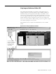
3 Using Integrated Architecture Builder (IAB) Integrated Architecture Builder is a graphical tool designed to help you configure and quote Logix-based control systems, including validation of DeviceNet cable power requirements. With IAB, you can build a control system using a wizard and other common Microsoft Windows tools such as tree views, drag-and-drop, and cut-copy-paste. IAB also allows you to open product manuals to help you configure a system.
4 About the National Electric Code Much of the information provided in this manual is representative of the capability of a DeviceNet network and its associated components. The National Electric Code (NEC), in the United States, and the Canadian Electric Code (CECode), in Canada, places limitations on configurations and the maximum allowable power/current that can be provided. Refer to Appendix A for details.
Table of Contents Chapter 1 Get Started What’s in This Chapter . . . . . . . . . . . . . . . . . . . . . . . . . . . . . . . . . . . . 1-1 Before You Begin. . . . . . . . . . . . . . . . . . . . . . . . . . . . . . . . . . . . . . . . . 1-2 Set Up a DeviceNet Network . . . . . . . . . . . . . . . . . . . . . . . . . . . . . . . 1-4 Basic DeviceNet network . . . . . . . . . . . . . . . . . . . . . . . . . . . . . . . 1-5 Understand the topology . . . . . . . . . . . . . . . . . . . . . . . . . . . . . . . .
Table of Contents ii Chapter 3 Make Cable Connections Prepare Cables . . . . . . . . . . . . . . . . . . . . . . . . . . . . . . . . . . . . . . . . . . . 3-1 Install Open-Style Connectors. . . . . . . . . . . . . . . . . . . . . . . . . . . . . . . 3-2 Install Mini/Micro Sealed Field-Installable Connectors . . . . . . . . . . 3-3 Install DeviceBox and PowerTap Taps. . . . . . . . . . . . . . . . . . . . . . . . 3-4 Install PowerTap Taps . . . . . . . . . . . . . . . . . . . . . . . . . . . . . . . . . .
Table of Contents iii Appendix A Understand Select NEC Topics Specify Article 725 Topics . . . . . . . . . . . . . . . . . . . . . . . . . . . . . . . . . A-1 Round (thick & thin) and Class 2 flat media . . . . . . . . . . . . . . . A-1 Class 1 flat media . . . . . . . . . . . . . . . . . . . . . . . . . . . . . . . . . . . . . A-1 Appendix B Power Output Devices Use DeviceNet Power Supplies to Operate Output Devices . . . . . . B-1 Noise or Transient Protection . . . . . . . . . . . . . . . . . . . .
Table of Contents iv Publication DNET-UM072C-EN-P - July 2004
Chapter 1 Get Started What’s in This Chapter This chapter introduces the DeviceNet cable system and provides a brief overview of how to set up a DeviceNet network efficiently. The steps in this chapter describe the basic tasks involved in setting up a network.
1-2 Get Started Before You Begin Before you begin laying out your DeviceNet network, take a few minutes to consider the following decisions you must make. 1. What control platform should I use? For help with choosing the correct control platform for the application, refer to Chapter 2 of the NetLinx Selection Guide, publication NETS-SG001.
Get Started 1-3 Decide whether to use DeviceLogix/EE-capable I/O to run internal, programmable logic within the actual devices for fast execution rates. Document the data table requirements for each node. This information will help you develop the control platform user program. 3.
1-4 Get Started program. Refer to the online help accompanying RSNetWorx for DeviceNet software for assistance in adding and configuring devices. Once you have added devices, use either RSNetWorx for DeviceNet software or the device’s hardware mechanism to commission a node for that device. Use RSNetWorx for DeviceNet software to create and download a scanlist to the master scanner. 6. How do I check system performance? To obtain Rockwell Automation’s off-line performance simulation tools, visit www.ab.
Get Started 1-5 Basic DeviceNet network This figure shows a basic DeviceNet network and calls out its basic components. 3,4 TR Power Supply trunk line TR drop lines 2 1 device or node D TR 2 terminating resistor Checklist 5 41829 Understand the topology Understand the Media 1 The DeviceNet cable system uses a trunk/drop line topology. TR TR You must terminate the trunk line at both ends with 121Ω, 1%, 1/4W or larger terminating resistors.
1-6 Get Started Understand the cable options You can connect components using three cable options. All Allen-Bradley media, including KwikLink, meets or exceeds the specifications defined in the ODVA DeviceNet Specification. Use this cable As Round (thick) the trunk line on the DeviceNet network with an outside diameter of 12.2 mm (0.48 in.). You can also use this cable for drop lines. Round (thin) the drop line connecting devices to the main line with an outside diameter of 6.9 mm (0.27 in.).
Get Started 1-7 Determine the maximum trunk line distance The maximum cable distance is not necessarily the trunk length only. It is the maximum distance between any two devices. TIP Round cable (both thick and thin) contains five wires: One twisted pair (red and black) for 24V dc power, one twisted pair (blue and white) for signal, and a drain wire (bare). Flat cable contains four wires: One pair (red and black) for 24V dc power; one pair (blue and white) for signal.
1-8 Get Started In most cases, the maximum distance should be the measurement between terminating resistors. However, if the distance from a trunk line tap to the farthest device connected to the trunk line is greater than the distance from the tap to the nearest terminating resistor (TR), then you must include the drop line length as part of the cable length. Measure the distance between the terminating resistors. TR tap tap tap tap 3m (9.843 ft) TR D D D D D drop 1m (3.
Get Started 1-9 Determine the cumulative drop line length The data rate you choose determines the trunk line length and the cumulative length of the drop line. The cumulative drop line length refers to the sum of all drop lines, thick or thin cable, in the cable system. This sum cannot exceed the maximum cumulative length allowed for the data rate used. Data rate 125k bit/s 250k bit/s 500k bit/s The maximum cable distance from any device on a branching drop line to the trunk line is 6m (20 ft).
1-10 Get Started About direct connection Wire Color Wire Usage Identity Round Usage Flat white CAN_H signal signal blue CAN_L signal signal bare drain shield n/a black V- power power red V+ power power Connect devices directly to the trunk line only if you can later remove the devices without disturbing communications on the cable system.This is called a “zero-length” drop, because it adds nothing (zero) when calculating cumulative drop line length.
Get Started 1-11 Mini/Micro field-installable quick-disconnect (sealed) connectors (round media only) Screw terminals connect the cable to the connector. See Chapter 3 for information about making cable connections. mechanical key Micro Female red 2 mechanical key drain 1 3 5 4 black blue 1 5 Mini Female drain blue white white 4 2 3 red 30489-M black Additional configurations are available. Refer to the On-machine Connectivity catalog, publication M115-CA001.
1-12 Get Started Plug-in field-installable (open) connectors Most open-style devices ship with an open-style connector included. These connectors are also shipped in packages of 10.
Get Started 2 Terminate the Network TR TR 1-13 The terminating resistor reduces reflections of the communication signals on the network. Choose your resistor based on the type of cable (round or flat) and connector (open or sealed) you use.
1-14 Get Started • open-style terminating resistors.
Get Started 1-15 Guidelines for supplying power 3 Supply Power power supply Use the power supply to power the DeviceNet cable system only. If a device requires a separate 24V power source other than the DeviceNet power source, you should use an additional 24V power source.
1-16 Get Started Use a power supply that has current limit protection as described in national codes such as NEC, Article 725. IMPORTANT To determine the required power supply current: 1. Add the current requirements of all devices drawing power from the network. For example: 6.3A 2. Add an additional 10% to this total to allow for current surge. e.g. 6.3A x 10% = 6.93A 3. Make sure the total of 2 is less than the minimum name-plate current of the power supply you are using. e.g. 6.
Get Started 1-17 The maximum allowable current applies to the sum of currents for all nodes on the drop line. As shown in the example on page Page 1-7, the drop line length refers to the maximum cable distance from any node to the trunk line, not the cumulative drop line length. • high maximum common mode voltage drop on the V- (black) and V+ (red) conductors – the voltage difference between any two points on the V- conductor must not exceed the maximum common mode voltage of 4.
1-18 Get Started Power supply 2 Add each device’s (D3, D4, D5) current together for power supply 2 (0.25+1.00+0.10=1.35A). Results 1.35A is the minimum name-plate current rating that power supply 2 should have. Remember to consider any temperature or environmental derating recommended by the manufacturer. Place the power supply DeviceNet networks with long trunk lines or with devices on them that draw large currents at a long distance sometimes experience difficulty with common mode voltage.
Get Started 1-19 A sample curve for a single, end-connected power supply is shown on the next page. Current (amperes) Figure 1.1 One Power Supply (End Segment) KwikLink Cable (Flat) NEC/CE Code Maximum Current Limit Length of trunk line, meters (feet) 41932 Network Length m (ft) Maximum Current (A) Network Length m (ft) Maximum Current (A) 0 (0) 8.00* 220 (722) 1.31 20 (66) 8.00* 240 (787) 1.20 40 (131) 7.01* 260 (853) 1.11 60 (197) 4.72* 280 (919) 1.03 300 (984) 0.
1-20 Get Started The following example uses the look-up method to determine the configuration for one end-connected power supply. One end-connected power supply provides as much as 8A near the power supply. power supply 30m (100 ft) 23m (75 ft) TR PT 106m (350 ft) 53m (175 ft) T T T T D1 D2 0.15A D3 0.30A D4 0.10A 0.10A TR = terminating resistor T = T-Port tap PT = PowerTap tap D = device TR 41833 1. Determine the total length of the network. 106m 2.
Get Started 1-21 Connect power supplies To supply power you will need to install and ground the power supplies. To install a power supply: ATTENTION Make sure the ac power source remains off during installation. 1. Mount the power supply securely allowing for proper ventilation, connection to the ac power source, and protection from environmental conditions according to the specifications for the supply. 2.
1-22 4 Get Started Ground the Network power supply You must ground the DeviceNet network at only one location. Follow the guidelines described below. ATTENTION To prevent ground loops, • For Round media - Ground the V- conductor, shield, and drain wire at only one place. • For Flat media - Ground the V- conductor at only one place. Do this at the power supply connection that is closest to the physical center of the network to maximize the performance and minimize the effect of outside noise.
Get Started Round media wiring terminal block CAN_H CAN_L drain VV+ V+ Vpower supply L1 L2 grd 1-23 Flat media wiring terminal block open-style connector* One Power Supply Wire Color Wire Usage Identity Round Usage Flat CAN_ CAN_L white CAN_H signal signal V- blue CAN_L signal signal bare drain shield n/a black V- power power red V+ power power V+ V+ Vpower supply 120V ac (typical) 41677 40186 enclosure *A micro style connector may be used for power supply connections
1-24 Get Started Use this checklist when you install the DeviceNet network. You should complete this checklist prior to applying power to your network. 5 Use the Checklist Total device network current draw does not exceed power supply current limit. Common mode voltage drop does not exceed limit. Number of DeviceNet nodes does not exceed 64 on one network.
Get Started 1-25 Spacing of DeviceNet cable from ac conductors, as specified in publication 1770-4.1. Both the programmable controller and DeviceNet scanner module are in run mode. IMPORTANT IMPORTANT * Devices default to node 63. Leave node 63 open to avoid duplicate node addresses when adding devices. Change the default node address after installation. If your DeviceNet system does not run properly, see the scanner module’s display and network and status LEDs for help in troubleshooting.
1-26 Get Started Notes: Publication DNET-UM072C-EN-P - July 2004
Chapter Integrated Architecture Builder (IAB) software can be used to lay out a DeviceNet System and generate a BOM. Download IAB from www.ab.com/logix/iab/. 2 Identify Cable System Components Use this chapter to identify and become familiar with the basic DeviceNet cable system components.
2-2 Identify Cable System Components TIP The catalog numbers listed in this document are not representative of the full range of available DeviceNet media products. For a complete list of DeviceNet media, refer to the On-machine Connectivity Catalog, publication M115-CA001.
Identify Cable System Components About Thick Cable 2-3 Thick cable, with an outside diameter of 12.2 mm (0.48 in.), is generally used as the trunk line on the DeviceNet network. Thick cable can be used for trunk lines and drop lines. High-flex thick cable offers greater flexibility than traditional thick cable. Additional configurations are available. Refer to the On-machine Connectivity catalog, publication M115-CA001.
2-4 Identify Cable System Components About Flat Cable KwikLink flat cable is physically keyed to prevent wiring mishaps. KwikLink cable is available in both heavy-duty and general purpose versions. All variations of KwikLink cable are unshielded and contain four conductors. Flat cable is used exclusively for the trunk line. Cl1 and Cl2 cables, Auxiliary power, the blue and white pair, and red and black pair are used in the manner shown here. side view dc power pair 16 AWG black red 5.3 mm (0.21 in.
Identify Cable System Components Class 2 (CL2) KwikLink General Purpose Cable Spool Size Catalog Number 75 m (246 ft) 1485C-P1K75 200 m (656 ft) 1485C-P1K200 420 m (1378 ft) 1485C-P1K420 Class 1 (CL1) KwikLink Power Cable Spool Size Catalog Number 75 m (246 ft) 1485C-P1L75 200 m (656 ft) 1485C-P1L200 420 m (1378 ft) 1485C-P1L420 Connect to the Trunk Line 2-5 Class 2 (CL2) General Purpose Cable: Well-suited for less-demanding applications than heavy-duty cable, this design features a micro
2-6 Identify Cable System Components You can connect to the trunk line through a: Trunk-line connection See page 2-7 • T-Port tap Trunk-line connection See page 2-8 • DeviceBox tap 31410-M • PowerTap 41867 2-9 • DevicePort tap 2-9 power supply 41868 • Thru-trunk DevicePort tap 41869 2-12 Open-style connector 2-13 41708 • Open-style tap 2-13 30849-M • KwikLink micro connector Publication DNET-UM072C-EN-P - July 2004 2-15 • KwikLink open-style connector 2-15
Identify Cable System Components 2-7 About the T-Port tap Description Catalog Number Mini T-port tap (right keyway) 1485P-P1N5-MN5R1 Mini T-port tap (left keyway) 1485P-P1N5-MN5L1 Mini T-port tap (w/micro drop connection 1485P-P1R5-MN5R1 The T-Port tap connects to the drop line with a mini or micro quick-disconnect style connector. Mini T-Port taps provide right or left keyway for positioning purposes. Mini T-Ports are also available with a micro (M12) drop connection.
2-8 Identify Cable System Components About the DeviceBox tap Description Catalog Number 2-port DeviceBox tap (thick trunk) 1485P-P2T5-T5 2-port DeviceBox tap (thin trunk) 1485P-P2T5-T5C 4-port DeviceBox tap (thick trunk) 1485P-P4T5-T5 4-port DeviceBox tap (thin trunk) 1485P-P4T5-T5C 8-port DeviceBox tap (thick trunk) 1485P-P8T5-T5 8-port DeviceBox tap (thin trunk) 1485P-P8T5-T5C DeviceBox taps use round media only for a direct connection to a trunk line.
Identify Cable System Components 2-9 About the PowerTap Description Catalog Number Thick trunk PowerTap tap 1485-P2T5-T5 Thin trunk PowerTap tap 1485T-P2T5-T5C The PowerTap can provide overcurrent protection to the thick cable, 7.5A for each trunk. (Country and/or local codes may prohibit the use of the full capacity of the tap.) You can also use the PowerTap tap with fuses to connect multiple power supplies to the trunk line without back-feeding between supplies.
2-10 Identify Cable System Components 4-Port DevicePort Tap with 2m Drop Line 5-pin fixed internal thread 5.5 Dia. (0.22 mm) micro-female connector J1 J2 48 mm 59 mm (1.9 in.) (2.3 in.) thin cable (2m) J3 30 mm (1.2 in.) J4 44 mm (1.7 in.) 98 mm (3.9 in.) 41838 8-Port DevicePort Tap with 2m Drop Line 88 mm (3.5 in.) J2 J3 5-pin fixed internal thread J1 5.5 Dia. (0.22 mm) J4 48 mm 59 mm (1.9 in.) (2.3 in.) thin cable (2m) J5 30 mm (1.2 in.) 44 mm (1.7 in.) J6 J7 J8 187 mm (7.4 in.
Identify Cable System Components 2-11 Mini DevicePorts Catalog Number 4-port DevicePort tap with mini drop connection 1485P-P4N5-M5 8-port DevicePort tap with mini drop connection 1485P-P8N5-M5 All device connections are mini female receptacles; only mini male connectors can interface with each port. Trunk connection is a mini male quick disconnect. 4-Port DevicePort tap with mini drop connection J2 5-pin mini female J1 connectors 5-pin mini male connector 48 mm (1.9 in.
2-12 Identify Cable System Components Thru-trunk DevicePort tap Description Catalog Number 4-port Thru-trunk DevicePort tap, mini male/mini female to mini female 1485P-P4N5-MN5 6-port Thru-trunk DevicePort tap, mini male/mini female to mini female 1485P-P6N5-MN5 Thru-trunk DevicePort taps are passive multiport taps which connect directly to the trunk. These DevicePort taps are offered with 4 or 6 quick-disconnect ports in sealed versions to connect up to 6 physical nodes.
Identify Cable System Components 2-13 About direct connection trunk line disconnect here Connect devices directly to the trunk line only if you can later remove the devices without disturbing communications on the cable system. drop line device with fixed open-style connector If a device provides only fixed-terminal blocks for its connection, you must connect it to the cable system by a drop line.
2-14 Identify Cable System Components Description Catalog number 5-pin linear plug (open; with jack screws) 1799-DNETSCON 5-pin linear plug (open; without jack screws) 1799-DNETCON 10-pin linear plug (open) 1787-PLUG1OR 5-pin linear to micro adapter 1799-DNC5MMS Some open-style connectors provide a temporary connection for a PC or other configurable tool using probe holes. For connection, insert the prongs of a probe cable into the probe holes of a connector.
Identify Cable System Components 2-15 About KwikLink Insulation Displacement Connectors (IDCs) Description Catalog Number NEMA 6P, 13; IP67 Micro module w/base 1485P-P1E4-R5 NEMA 1; IP60 Micro module w/base (no gaskets) 1485P-P1H4-R5 Open-style module w/base (no gaskets) 1485P-P1H4-T4 KwikLink General Purpose Connector, Micro1 1485P-K1E4-R5 1 Use this connector also with KwikLink General Purpose Flat Cable (1485C-P1K).
2-16 Identify Cable System Components Use Preterminated Cables Using preterminated cable assemblies saves you the effort of stripping and wiring connectors to the cable ends. Because pre-terminated cables are normally factory-tested, using them also helps reduce wiring errors. TIP Additional cable lengths and configurations, other than those shown, are available from Rockwell Automation. About thick cable You can order thick cable in multiple lengths with mini connectors at each end.
Identify Cable System Components 2-17 About thin cable Additional configurations are available. Refer to the On-machine Connectivity catalog, publication M115-CA001. Preterminated thin cable assemblies for use as a drop line are available with various connectors in lengths of 1, 2, 3, 4, 5 and 6m. Preterminated thin cable assemblies can also be used as trunk lines.
2-18 Identify Cable System Components Connecting to a DevicePort tap or Micro T-Port tap from a sealed device specified length mini female plug 90°micro male plug Additional configurations are available. Refer to the On-machine Connectivity catalog, publication M115-CA001.
Identify Cable System Components 2-19 Connecting to micro T-Port taps device device Additional configurations are available. Refer to the On-machine Connectivity catalog, publication M115-CA001.
2-20 Identify Cable System Components Connecting to a KwikLink tap from a sealed device specified length micro female plug 90°micro male plug Additional configurations are available. Refer to the On-machine Connectivity catalog, publication M115-CA001.
Identify Cable System Components 2-21 Connecting to a KwikLink Cable Drop or Mini-style Pigtail Drop Specified Length Additional configurations are available. Refer to the On-machine Connectivity catalog, publication M115-CA001.
2-22 Identify Cable System Components About terminators Wire Color Wire Usage Identity Round Usage Flat white CAN_H signal signal blue CAN_L signal signal bare drain shield n/a black V- power power red V+ power power Electrically stabilize your DeviceNet communication with terminating resistors. You must terminate the trunk line on each end with a 121ohms, 1%, 1/4W or larger resistor.
Identify Cable System Components 2-23 Sealed and unsealed flat media terminators These terminators have an IDC base and are shipped with an end cap. Unsealed terminators do not have gaskets.
2-24 Identify Cable System Components Notes: Publication DNET-UM072C-EN-P - July 2004
Chapter 3 Make Cable Connections Prepare Cables In Chapter 1, you determined the required lengths of trunk line and drop line segments for your network. To cut these segments from reels of thick, thin and flat cable, use a sharp cable cutter and provide sufficient length in each segment to reduce tension at the connector. TIP IMPORTANT Select an end of the cable segment that has been cleanly cut. The positions of the color-coded conductors should match the positions at the face of the connector.
3-2 Make Cable Connections Install Open-Style Connectors To attach a plug-in open-style connector to a round media (thick or thin) trunk line: 1. Strip 65 mm (2.6 in.) to 75 mm (2.96 in.) of the outer jacket from the end of the cable, leaving no more than 6.4 mm (0.25 in.) of the braided shield exposed. 6.4 mm (0.25 in.) jacket braided shield 65 mm (2.6 in.) 41840 2. Wrap the end of the cable with 38 mm (1.5 in.
Make Cable Connections Wire Color Wire Identity Usage Round white CAN_H signal blue CAN_L signal bare drain shield black V- power red V+ power 6. Tighten the clamping screws to secure each conductor. The male contacts of the device connector must match the female contacts of the connector.
3-4 Make Cable Connections 7. Attach wires to the connector using screw terminals as seen in the following diagram. The following illustration shows a mini male and female connector. Connections are similar for micro connectors. TIP male connector black power conductors red signal conductors bare female connector bare black red white power conductors white blue signal condctors bare Rear View Rear View blue bare 41848 8. Screw the enclosure body to the connector. 9.
Make Cable Connections 3-5 c. Strip 8.1 mm (0.32 in.) of the insulation from the end of each of the insulated conductors. heat shrink 8.1 mm (0.32 in.) 41845 3. Attach cables to the enclosure. a. Loosen the large gland nuts. b. Insert cables through the large cable glands so that about 3.3 mm (0.13 in.) of the cable jackets extend beyond the locking nut toward the inside of the enclosure. c. Hold the hex flange in place with the cable gland wrench, and firmly tighten the gland nut.
3-6 Make Cable Connections IMPORTANT The two fuses used in the PowerTap tap are 7.5A fast-acting automotive type (ACT type), which you can order from your local fuse supplier. To attach a PowerTap: 1. Cut and strip the thick cable back approximately 100 mm (4 in.). Wire Color Wire identity Use white CAN_H signal blue CAN_L signal bare drain shield black V- power red V+ power 100mm (4 in) 31512-M 2. Loosen the gland nut.
Make Cable Connections 3-7 5. Firmly twist the bare wire ends to eliminate loose strands. ATTENTION Be certain that you use insulating tubing (included with the accessory kit) on bare drain wire. 6. Loop each bare wire as shown below so you may insert the terminal block into the clamping cavity. PowerTap Tap - 1485T-P2T5-T5 power supply trunk trunk 41758 7. Firmly tighten the terminal block screw to clamp the bare wire end in place. 8.
3-8 Make Cable Connections Install DeviceBox Taps The DeviceBox tap contains terminal blocks that connect the trunk line and as many as eight drop lines. It is used only with round media. Gland nuts secure the cables entering the ports of the DeviceBox tap.To attach a DeviceBox tap: 1. Cut the required lengths from reels of trunk line using a sharp cable cutter providing sufficient length in each segment to reduce tension at the connection.
Make Cable Connections Install DevicePort Taps 3-9 The DevicePort tap connects as many as eight quick-disconnect cables to the trunk line. J1 J2 J5 J6 J3 J4 2 m (6.56 ft) J7 J8 41852 Connect Drop Lines Drop lines, made up of thick or thin cable, connect devices to taps.
3-10 Make Cable Connections 4. Make the connection to the trunk line last. IMPORTANT Install KwikLink Cable and KwikLink Heavy-Duty Connectors Follow the wiring diagrams for each connection, and make sure you do not exceed the maximum allowable length from the device connection to the trunk connection. Install KwikLink cable with the wider, flat edge of the cable on the bottom.
Make Cable Connections 3-11 2. Close the hinged assembly, applying pressure until the latch locks into place. IMPORTANT The latch has two catches. The first catch loosely holds the connector on the cable. The second catch needs more pressure applied to close the connector tightly. If the cable is not in the correct position, the connector will not close. 30475-M 3. Make sure the cable is straight before moving on to step four.
3-12 Make Cable Connections Check the cable position prior to tightening the screws. Tighten screws by the latch first 30476-M 6. Drive the IDC contacts into the cable by tightening down the two screws in the center of the base assembly. . IMPORTANT The module should not be removed after connection is made. Determine the exact placement of the connector before engaging the IDC contacts. Take care to avoid stripping the screws. Ample torque should be 5.56 N (15 in-lbs).
Make Cable Connections 3-13 8. Line up the keyed rectangular holes of the micro/open/terminator connection interface with the matching posts on the base and snap the micro module into place. Optional: Secure the micro/open/terminator module by driving an 8-32 x 1-3/4 screw through each of the two remaining mounting holes.
3-14 Make Cable Connections – You must cut or heat shrink the drain wire when you use round 5-wire (thin) drop cable. red Wire Color Wire identity Use Flat white CAN_H signal signal blue CAN_L signal signal bare drain shield n/a black V- power power red V+ power power white blue black red white blue black Use only with KwikLink The round 4-wire KwikLink drop cable (gray) has no drain wire.
Make Cable Connections 3-15 30481 3. Repeat the end cap installation process as outlined previously. Close the IDC base and continue with connection as illustrated in the standard installation instructions starting on page 3-10.
3-16 Make Cable Connections Pinout diagrams for mini and micro connections to the power cable are shown below.
Make Cable Connections 3-17 Connect Power Supplies to Class 1, 8A System KwikLink Flat Media For a Class 1, 8A System, power may only be interfaced with the network using a KwikLink open-style connector. Class 2, 4A System For a Class 2, 4A System, power may be applied to the network using KwikLink micro or open-style connectors.
3-18 Make Cable Connections Notes: Publication DNET-UM072C-EN-P - July 2004
Chapter 4 Determine Power Requirements In this chapter, we describe two methods for determining your system’s power requirements: • the look-up method • the full calculation method Try the look-up method first, then move on to the full calculation method if you cannot meet your configuration requirements.
4-2 Determine Power Requirements Class 2 (CL2) Cable Per NEC specifications for a Class 2 circuit (see NEC Article 725), the energy in the circuit anywhere is limited to 100 VA and the cable’s jacketing must have a 300V minimum isolation rating. Based on a 30V dc system, your circuit would be limited to 3.3A. The DeviceNet specification indicates the power source be a maximum of 24V dc. Applying this to a Class 2 circuit running at 24V dc, the maximum allowable current is 4A.
Determine Power Requirements Use the Look-up Method 4-3 To determine if you have adequate power for the devices in your cable system, see the following examples and figures. You have enough power if the total load does not exceed the value shown by the curve or the table. In a worst-case scenario, all of the nodes are together at the opposite end of the power supply. 41710 TIP This method may underestimate the capacity of your network by as much as 4 to 1.
4-4 Determine Power Requirements Current (amperes) Figure 4.1 One Power Supply (End Segment) Round Cable (Thick). Assumes all nodes are at the opposite end of the cable from the power supply. NEC/CE Code Maximum Current Limit 41931 Length of trunk line, meters (feet) Network Length m (ft) Maximum Current (A) Network Length m (ft) Maximum Current (A) 0 (0) 8.00* 240 (787) 1.28 20 (66) 8.00* 260 (853) 1.19 40 (131) 6.53* 280 (919) 1.10 60 (197) 4.63* 300 (984) 1.03 80 (262) 3.
Determine Power Requirements 4-5 Current (amperes) Figure 4.2 One Power Supply (End Segment) KwikLink Cable (Flat). Assumes all nodes are at the opposite end of the cable from the power supply. NEC/CE Code Maximum Current Limit Length of trunk line, meters (feet) 41932 Network Length m (ft) Maximum Current (A) Network Length m (ft) Maximum Current (A) 0 (0) 8.00* 220 (722) 1.31 20 (66) 8.00* 240 (787) 1.20 40 (131) 7.01* 260 (853) 1.11 60 (197) 4.72* 280 (919) 1.03 300 (984) 0.
4-6 Determine Power Requirements Figure 4.3 Two Power Supplies, (One-End Connected, One Middle-Connected); Two Cable Segments, Round Cable (Thick). Current (amperes) Segment A NEC/CE Code Maximum Current Limit Segment B Total Length of trunk line, meters (feet) 41933 Power Supply A Power Supply B Network Length m (ft) Maximum Current (A) Network Length m (ft) Maximum Current (A) Network Length m (ft) Maximum Current (A) Network Length m (ft) Maximum Current (A) 0 (0) 8.00* 260 (853) 8.
Determine Power Requirements 4-7 Figure 4.4 Two Power Supplies, (One End-Connected, One Middle-Connected); Two Cable Segments, KwikLink Cable (Flat). Current (amperes) Segment A NEC/CE Code Maximum Current Limit Segment B Total Length of trunk line, meters (feet) 41934 Segment Supply A Segment Supply B Network Length m (ft) Maximum Network Current (A) Length m (ft) Maximum Current (A) Network Length m (ft) Maximum Current (A) Network Length m (ft) Maximum Current (A) 0 (0) 8.
4-8 Determine Power Requirements Current (amperes) Figure 4.5 Two End-Connected Power Supplies, Round Cable (Thick). NEC/CE Code Maximum Current Limit Length of trunk line, meters (feet) 41935 Network Length m (ft) Maximum Current (A) Network Length m (ft) Maximum Current (A) 0 (0) 8.00* 260 (853) 4.25* 20 (66) 8.00* 280 (919) 3.96 40 (131) 8.00* 300 (984) 3.70 60 (197) 8.00* 320 (1050) 3.48 80 (262) 8.00* 340 (1115) 3.28 100 (328) 8.00* 360 (1181) 3.10 120 (394) 8.
Determine Power Requirements 4-9 Current (amperes) Figure 4.6 Two End-Connected Power Supplies, KwikLink Cable (Flat) NEC/CE Code Maximum Current Limit 41936 Length of trunk line, meters (feet) Network length m (ft) Maximum current (A) Network length m (ft) Maximum current (A) 0 (0) 8.00* 220 (722) 4.69* 20 (66) 8.00* 240 (787) 4.30* 40 (131) 8.00* 260 (853) 3.97 60 (197) 8.00* 280 (919) 3.69 80 (262) 8.00* 300 (984) 3.44 100 (328) 8.00* 320 (1050) 3.23 120 (394) 8.
4-10 Determine Power Requirements Figure 4.7 One Power Supply (End Segment) Round Cable (Thin) Current (amperes) NEC/CE Code Maximum Current Limit Length of trunk line, meters (feet) Publication DNET-UM072C-EN-P - July 2004 Network length m (ft) Maximum current (A) 0 (0) 3.00 10 (33) 3.00 20 (66) 3.00 30 (98) 2.06 40 (131) 1.57 50 (164) 1.26 60 (197) 1.06 70 (230) 0.91 80 (262) 0.80 90 (295) 0.71 100 (328) 0.
Determine Power Requirements 4-11 One power supply (end-connected) The following example uses the look-up method to determine the configuration for one end-connected power supply. One end-connected power supply provides as much as 8A near the power supply. power supply 23m (75 ft) TR PT 30m (100 ft) 106m (350 ft) 53m (175 ft) T T T T D1 D2 0.15A D3 0.30A D4 0.10A 0.10A TR = terminating resistorT = T-Port tap PT = PowerTap tapD = device TR 41833 1.
4-12 Determine Power Requirements Results Since the total current does not exceed the maximum allowable current, the system will operate properly (0.65A ≤ 2.47A).
Determine Power Requirements 4-13 Section 2 = 140m (2.14A) IMPORTANT Results Section 1 + Section 2 < 3.6A. This is < 4A for NEC/CECode compliance. Section 1 is overloaded because the total current exceeds the maximum current (2.85A > 2.14A). Section 2 is operational since the total current does not exceed the maximum current (0.75A < 2.14A). Balance the system by moving the power supply toward the overloaded section (section 1). Then recalculate each section.
4-14 Determine Power Requirements 4. Add each device’s current together in section 1. 1.10+1.25+0.50 = 2.85A 5. Add each device’s current together in section 2. 0.25+0.25+0.25 = 0.75A 6. Find the value next largest to each section’s length using Figure 4.1 on Page 4-4 to determine the approximate maximum current allowed for each section.
Determine Power Requirements 4-15 Adjusting the configuration To make the system operational, you can: • • • • • move the power supply in the direction of the overloaded section move higher current loads as close to the supply as possible move devices from the overloaded section to another section shorten the overall length of the cable system perform the full-calculation method for the segment described later in this chapter for the non-operational section • add a second power supply to the cable system
4-16 Determine Power Requirements .
Determine Power Requirements power supply power supply 274m (900 ft) 122m (400 ft) 76m (250 ft) 30m (100 ft) TR PT 4-17 T T T T T D1 0.25A D2 0.50A D3 0.10A D4 0.25A D5 1.00A 122m (400 ft) 76m (250 ft) 30m (100 ft) T PT TR D6 0.10A TR = terminating resistorT = T-Port tap PT = PowerTap D = device 41861 1. Determine the total length of the network. 274m 2. Add each device’s current together to find the total current. 0.25+0.50+0.10+0.25+1.00+0.10 = 2.20A 3.
4-18 Determine Power Requirements Two Power supplies (not end-connected) in parallel with no V+ break The following example uses the look-up method to determine the configuration for two power supplies that are not end-connected. This configuration provides the most power to the cable system. You must use diodes at the power taps to prevent back-feeding of the power supplies. Check your national and local codes for any restrictions on the use of parallel power supplies.
Determine Power Requirements 4-19 3. Find the value next largest to the length of section 3 using Figure 4.3 on page 4-6 to determine the approximate maximum current allowed (approximately). 140m (3.40A) IMPORTANT Results If the total current in the section exceeds the maximum current, move the power supply closer to the end and repeat steps 1-3 until the total current in the section is less than the maximum allowable current.
4-20 Determine Power Requirements 9. Find the value next largest to the length of section 2 using Figure 4.3 on page 4-6 to determine the approximate maximum current allowed. 280m (7.69A) IMPORTANT Results If the total current in the section exceeds the maximum current, move the power supplies closer together and repeat steps 7-9 until the total current in the section is less than the maximum allowable current.
Determine Power Requirements 4-21 A supply that is not end-connected creates two sections of trunk line. Evaluate each section independently. Use the Equation SUM {[(Ln x (Rc)) + (Nt x (0.005))] x In} < 4.65V Term Ln Rc Definition L = The distance (m or ft) between the device and the power supply, excluding the drop line distance. n = The number of a device being evaluated, starting with one for the device closest to the power supply and increasing by one for the next device.
4-22 Determine Power Requirements One power supply (end-connected) Example using thick cable The following example uses the full calculation method to determine the configuration for one end-connected power supply on a thick cable trunk line. • Device 1 and Device 2 cause the same voltage drop but Device 2 is twice as far from the power supply and draws half as much current.
Determine Power Requirements 4-23 One power supply (middle-connected) Example using thick cable This example is used to check loading on both sides of a middle-connected supply on a thick cable trunk line. Keep the loads, especially the higher ones, close to the power supply. If the device location is fixed, put the power supply in the center of the highest current concentration.
4-24 Determine Power Requirements 3. Find the voltages for each device in section 2 using the equation for thick cable. SUM {[(Ln x (0.0045)) + (Nt x (0.005))] x In} < 4.65V. D4 A.[(200 x (0.0045)) + (1 x (0.005))] x 0.25 = 0.23V 0.25A B.[(400 x (0.0045)) + (2 x (0.005))] x 1.5 = 2.72V D5 1.5A C.[(800 x (0.0045)) + (3 x (0.005))] x 0.5 = 1.81V D6 0.5A 4. Add each device’s voltage together to find the total voltage for section 2. 0.23 + 2.72 + 1.81 = 4.
Determine Power Requirements 4-25 D.[(1100 x (0.0045)) + (4 x (0.005))] x 0.25 = 1.24V 2. Add each device’s voltage together to find the total voltage for section 1. 0.11 + 0.45 + 0.79 + 1.24= 2.59V 3. Find the voltages for each device in section 2 using the equation for thick cable. SUM {[(Ln x (0.0045)) + (Nt x (0.005))] x In} < 4.65V. D5 A.[(100 x (0.0045)) + (1 x (0.005))] x 1.5 = 0.68V 1.5A D6 B.[(500 x (0.0045)) + (2 x (0.005))] x 0.5 = 1.13V 0.5A 4.
4-26 Determine Power Requirements Notes: Publication DNET-UM072C-EN-P - July 2004
Chapter 5 Correct and Prevent Network Problems Use this chapter if you are experiencing problems with network operation. In this chapter, we tell you how to locate and correct problems associated with improper system design. ATTENTION General Troubleshooting Tips Verify that all devices on the network have been certified by the Open DeviceNet Vendor Association (ODVA), and carry the DeviceNet Conformance Check on their nameplate.
5-2 Correct and Prevent Network Problems Use Rockwell Automation’s Media Checker (catalog number 1788-MCHKR; available from your local Rockwell Automation distributor) to test network problems that result from miswiring, loose connections, opens or shorts. Be careful when setting network addresses and baud rates. Incorrectly set addresses or baud rates will cause other nodes to appear to be bad.
Correct and Prevent Network Problems Use the following tips to diagnose and correct some of the most commonly occurring network problems. Diagnose Common Problems TIP problem common mode problems 5-3 Most devices have some type of status display, such as LEDs or alpha-numeric message displays. If any of your devices display error messages, refer to the documentation provided by the manufacturer to interpret the error codes.
5-4 Correct and Prevent Network Problems problem bus traffic problems symptom • nodes stop communicating • device times out do this • check scanner configuration to ensure scan rate is set correctly − inter-scan/delay scan interval too short can cause device timeouts − inter-scan/delay scan interval too long can reduce system performance and make inefficient use of available bandwidth • check change-of-state devices consuming excessive bandwidth • increase production inhibit time or change these devices
Correct and Prevent Network Problems Check System Design 5-5 You can avoid many network problems by verifying that you have properly designed your network. Begin by walking the physical network, and making a sketch of your network layout. Then follow the checklist below. Table 5.1 Troubleshooting your system design check to ensure that number of nodes you do not exceed the recommended maximum of 64 nodes.
5-6 Correct and Prevent Network Problems Table 5.1 Troubleshooting your system design check to ensure that cables cables are properly routed. Verify that all cables: • are kept away from power wiring, as described in publication 1770-4.1 • are not draped on electric motors, relays, contactors, solenoids, or other moving parts • are not constrained so that cables place excessive tension on connectors connectors connectors are properly installed and are tight.
Correct and Prevent Network Problems Use Terminating Resistors 5-7 The DeviceNet network may operate unpredictably without terminating resistors installed at each end of the trunk cable. You can order terminating resistors, part number 1485A-C2, from your local Rockwell Automation distributor. To install terminating resistors: 1. Attach a 121Ω, 1%, 1/4W or larger terminating resistor at each end of the trunk cable, across the blue (CAN_H) and white (CAN_L) wires of the cable. 2.
5-8 Correct and Prevent Network Problems When choosing a power supply, keep the following tips in mind: IMPORTANT We recommend that the DeviceNet power supply be used to power only the DeviceNet network. • The thin wire trunk line is rated to 3A current flow. The thick wire trunk line is rated to 8A current flow. In North America, however, current is limited to 4A.
Correct and Prevent Network Problems 5-9 Table 5.2 lists nominal voltage readings. TIP Because the differential voltages are constantly shifting among the three wires, the voltages on your scope trace may differ from the nominal voltages shown in Table 5.2. These voltages assume no common mode effect on the Vand are for reference only. Table 5.
5-10 Correct and Prevent Network Problems Notes: Publication DNET-UM072C-EN-P - July 2004
Appendix A Understand Select NEC Topics Be aware that the following topics from the National Electrical Code (NEC) 725 (revision 1999) impact the configuration and installation of DeviceNet systems in the United States. There also may be additional NEC sections and local codes that you must meet. Other codes exist outside of the United States that may also affect your installation.
A-2 Understand Select NEC Topics Notes: Publication DNET-UM072C-EN-P - July 2004
Appendix B Power Output Devices Use DeviceNet Power Supplies to Operate Output Devices You can power some output devices on the DeviceNet network. The application must allow the voltage to remain within the DeviceNet specification limits of 11-25V dc. Because most actuators usually require more power than is practically available from the DeviceNet network, they must be powered by a separate power supply.
B-2 Power Output Devices Noise or Transient Protection The typical actuators used in DeviceNet control systems utilize inductive coils that generate transients when de-energized. You must use appropriate protection to suppress transients during coil de-energization. Add a diode across the inductive coil to suppress transients on the actuator’s dc coils. Use a MOV varistor module suppressor for a 24V dc coil if this added drop out time with the diode is unacceptable.
Index Numerics 10 pin linear plug 1-12 5 pin linear plug 1-12 A additional resources Preface-2 adequate power worst case scenario 4-3 adjusting the configuration 4-15 audience Preface-1 auxiliary power cable diagram 3-15 installation 3-15 C cable installation KwikLink 3-10 cable position Kwiklink 3-11 cable preparation 3-1 cables maximum distance 1-7 determining 1-8 preterminated thick 2-16 thin 2-17 system current 4-21 CECode current boost configuration example 4-15 checking system design 5-3 circuit Cla
2 Index open-style attaching to trunk line 3-2 fixed 3-9 hard wire 3-9 plug-in 3-9 pinouts 3-1 sealed-style attaching to trunk line 3-3 micro-style 1-10, 3-9 mini-style 1-10, 3-9 current boost example 4-15 cable system maximum 4-21 nominal device 4-21 maximum allowable one power supply (end connected) example 4-11 one power supply (middle connected) example 4-12 segment between two power supplies figure 4-10 two power supplies (end connected) example 4-16 two power supplies (not end connected) example 4-1
Index preterminated thick cable 2-16 thin cable 2-17 connecting to DeviceBox tap 2-18 connecting to DevicePort tap 2-18 connecting to T-Port tap 2-17 thick cable 2-3 thin cable 2-3 T-Port tap 2-7 diodes transient protection 1-2 direct connection connecting to trunk line 2-6 description 1-10, 2-13 diagram 1-10, 2-13 open-style fixed 2-6 plug-in 2-6 zero-length drop 1-10 distance maximum cable 1-7 determining 1-8 drift temperature 1-15 time 1-15 drop line allowable current 1-16 connection types open-style
4 Index full calculation method description 4-20 equations 4-21 examples power supplies one end connected 4-22 middle connected 4-23 full-calculation method 4-12 fusing PowerTap tap 3-5 G grounding the network 5-7 guidelines supplying power 1-15 H hard wire taps installing DeviceBox tap 3-4 PowerTap tap 3-4 high inrush currents DeviceNet power 1-2 hydraulic solenoid valves output power 1-1 I IDC’s KwikLink connectors 2-15 installation auxiliary power cable 3-15 KwikLink end cap 3-14 KwikLink connector
Index look-up method configuration one power supply end connected 4-11 examples NEC/CECode current boost configuration 4-15 power supply one end connected 4-11 middle connected 4-12 two end connected 4-16 not end connected 4-18 figures power supply two middle segment 4-10 making system operational 4-15 5 section 725 1-1 NEC regulations power conductors 4-2 NEC specifications class 1 cable 4-1 class 2 cable 4-2 NEC/CECode current boost configuration 4-15 NEMA rating KwikLink terminating resistor sealed
6 Index output devices minimum required operating voltage 1-1 powering 1-1 output power hydraulic solenoid valves 1-1 motor starter coils 1-1 noise or transient protection 1-2 pneumatic valves 1-1 P parallel application power supplies 1-16 pluggable screw-connector installation 3-2 plug-in connector open-style 1-10 pneumatic valves output power 1-1 power determining using look-up method 1-18, 4-3 limitations 1-1 power cable diagram KwikLink 3-15 KwikLink installation 3-15 power conductors NEC regulations
Index R rating drop line 1-16 thick cable 1-16 regulation line 1-15 load 1-15 resistance nominal contact 4-21 resistor connection verification 1-13 resistors usage definition 1-13 rise time power supply 1-15 round cable wire contents 1-7 S sealed device connecting to KwikLink micro t-port tap 2-19 sealed terminating resistor KwikLink NEMA rating 1-14 sealed-style connector attaching to trunk line 3-3 micro-style 1-10, 3-9 mini-style 1-10, 3-9 single power supply minimum name-plate current 1-16 software
8 Index connecting to a DevicePort tap micro male (90) to micro female 2-18 micro male (90) to mini female 2-18 connecting to a T-Port tap mini male to micro female 2-17 mini male to micro male (90) terminating 1-7, 2-5 two power supplies current chart end segment KwikLink 4-9 KwikLink cable 4-7 round cable thick 4-6 2-17 mini male to mini female 2-17 description 2-17 diagram 2-17 size 1-6 spool size 2-3 time drift 1-15 total allowable current class 1 flat cable 1-15 thick cable class 2 flat cable 1
How Are We Doing? Your comments on our technical publications will help us serve you better in the future. Thank you for taking the time to provide us feedback. You can complete this form and mail (or fax) it back to us or email us at RADocumentComments@ra.rockwell.com Pub. Title/Type DeviceNet Media Design and Installation Guide Cat. No. all DeviceNet Pub. No. DNET-UM072C-EN-P Pub. Date July 2004 Part No. 957859-79 Please complete the sections below.
PLEASE FASTEN HERE (DO NOT STAPLE) PLEASE FOLD HERE NO POSTAGE NECESSARY IF MAILED IN THE UNITED STATES BUSINESS REPLY MAIL FIRST-CLASS MAIL PERMIT NO.
Rockwell Automation provides technical information on the web to assist you in using our products. At http://support.rockwellautomation.com, you can find technical manuals, a knowledge base of FAQs, technical and application notes, sample code and links to software service packs, and a MySupport feature that you can customize to make the best use of these tools.