
Design Installation Guide Owner's manual


Publication DNET-UM072C-EN-P - July 2004
Correct and Prevent Network Problems 5-5
Check System Design
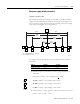
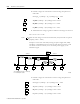
You can avoid many network problems by verifying that you have properly
designed your network. Begin by walking the physical network, and making a
sketch of your network layout. Then follow the checklist below.
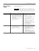
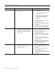
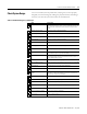
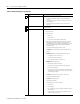
Table 5.1 Troubleshooting your system design
check to ensure that
number of nodes you do not exceed the recommended maximum of 64 nodes. The practical limit
of DeviceNet nodes may be 61 devices, since you should allow one node each
for the scanner, the communication interface module, and an open node at
node 63.
cumulative drop line length you do not exceed the recommended maximum
individual drop line length you do not exceed the recommended maximum of 6m (20ft)
branched drop line length you do not exceed the recommended maximum
total trunk length you do not exceed the recommended maximum
termination resistors the trunk line is terminated at both ends with a 121Ω, 1%, 1/4W or larger
resistor
power supply cable you are using the proper cable length and gauge
power cable to the trunk line you are using the proper cable size and length
power supply cable you do not exceed recommended electrical noise levels. Use an oscilloscope or
power disturbance analyzer to spot-check the cabling
V- and shield wires these wires are properly connected and grounded. Break the shield to V-
connection at the power supply and use an ohmmeter to verify resistance is
less than 1MΩ with 24V dc removed.
earth ground wire you are using the proper length and gauge
CAN_L and CAN_H to shield
and/or V- wires
no shorts are present. Use an ohmmeter to verify resistance is less than 1MΩ.
total current load the current load does not exceed the power supply rating
trunk and drop line currents you do not exceed recommended current limits
voltage at middle and ends of
network
voltage measures higher than 11V dc but lower than 25V dc. If voltage falls
below 15V dc, a common mode problem may exist on the network. Refer to
Chapter 4 of this manual for more information.
lead dress at junction boxes you have made proper connections
connectors connectors are screwed together tightly
glands glands are screwed together tightly
glands there is no foreign material (e.g., electrical tape, RTV sealant) in gland
nodes nodes do not contact extremely hot or cold surfaces
physical media (prior to applying
power)
there are no loose wires or coupling nuts
physical media no opens or shorts are present.