
Design Installation Guide Owner's manual

Publication DNET-UM072C-EN-P - July 2004
Get Started 1-17
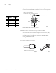
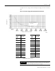
The maximum allowable current applies to the sum of currents for all nodes on
the drop line. As shown in the example on page Page 1-7, the drop line length
refers to the maximum cable distance from any node to the trunk line, not the
cumulative drop line length.
• high maximum common mode voltage drop on the V- (black) and V+
(red) conductors
– the voltage difference between any two points on the V- conductor must
not exceed the maximum common mode voltage of 4.65V
• voltage range between V- and V+ at each node within 11 to 25V
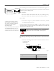
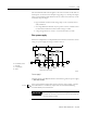
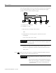
Size a power supply
Follow the example below to help determine the minimum continuous current
rating of a power supply servicing a common section.
Power supply 1
Add each device’s (D1, D2) DeviceNet current draw together for power supply
1 (1.50+1.05=2.55A)
2.55A is the minimum name-plate current rating that power supply 1 should
have. Remember to consider any temperature or environmental derating
recommended by the manufacturer.
power
supply 1
power
supply 2
152m
(500 ft)
122m
(400 ft)
122m
(400 ft)
30m
(100 ft)
30m
(100 ft)
60m
(200 ft)
TR
TR
PT PTTT TTT
D1 D2 D3 D4 D5
1.50A 1.05A 0.25A 1.00A 0.10A
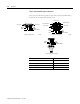
TR = terminating resistor
T = T-Port tap
PT = PowerTap tap
D = device
break V+ (red wire) here to separate
both halves of the network
41831
IMPORTANT
This derating factor typically does not apply when you
consider the maximum short circuit current allowed by the
national and local codes.
Results