
Design Installation Guide Owner's manual

Publication DNET-UM072C-EN-P - July 2004
4-6 Determine Power Requirements
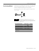
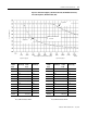
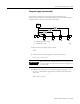
Figure 4.3 Two Power Supplies, (One-End Connected, One Middle-Connected);
Two Cable Segments, Round Cable (Thick).
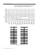
Network
Length
m (ft)
Maximum
Current (A)
260 (853)
8.00*
280 (919)
7.69*
300 (984)
7.21*
320 (1050)
6.78*
340 (1115)
6.41*
360 (1181)
6.07*
380 (1247)
5.76*
400 (1312)
5.49*
420 (1378)
5.24*
440 (1444)
5.01*
460 (1509)
4.80*
480 (1575)
4.73*
500 (1640)
4.66*
Segment A
Segment B
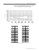
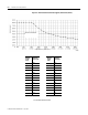
Network
Length
m (ft)
Maximum
Current (A)
0 (0)
8.00*
20 (66)
8.00*
40 (131)
8.00*
60 (197)
7.38*
80 (262)
5.71*
100 (328)
4.66*
120 (394)
3.94
140 (459)
3.40
160 (525)
3.00
180 (591)
2.68
200 (656)
2.43
220 (722)
2.22
240 (787)
2.08
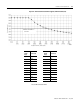
Network
Length
m (ft)
Maximum
Current (A)
260 (853)
1.89
280 (919)
1.76
300 (984)
1.64
320 (1050)
1.54
340 (984)
1.46
360 (1050)
1.38
380 (1247)
1.31
400 (1312)
1.24
420 (1378)
1.18
440 (1444)
1.13
460 (1509)
1.08
480 (1575)
1.07
500 (1640)
1.05
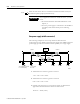
Power Supply B
Total Length of trunk line, meters (feet)
Current (amperes)
NEC/CE Code Maximum
Current Limit
∗
Exceeds NEC CL2/CECode 4A limit.
∗
Exceeds NEC CL2/CECode 4A limit.
Power Supply A
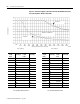
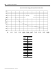
Network
Length
m (ft)
Maximum
Current (A)
0 (0)
8.00*
20 (66)
8.00*
40 (131)
8.00*
60 (197)
8.00*
80 (262)
8.00*
100 (328)
8.00*
120 (394)
8.00*
140 (459)
8.00*
160 (525)
8.00*
180 (591)
8.00*
200 (656)
8.00*
220 (722)
8.00*
240 (787)
8.00*
41933