
Design Installation Guide Owner's manual

Publication DNET-UM072C-EN-P - July 2004
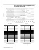
4-12 Determine Power Requirements
Since the total current does not exceed the maximum allowable current, the
system will operate properly (0.65A ≤ 2.47A).
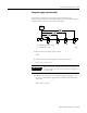
One power supply (middle-connected)
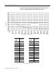
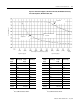
The following example uses the look-up method to determine the
configuration for one middle-connected power supply. One middle-connected
power supply provides the maximum current capability for a single supply.
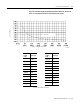
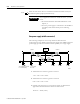
1. Add each device’s current together in section 1.
1.10 + 1.25 + 0.50 = 2.85A
2. Add each device’s current together in section 2.
0.25 + 0.25 + 0.25 = 0.75A
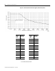
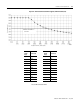
3. Find the value next largest to each section’s length to determine the
approximate maximum current allowed for each section.
Section 1 = 140m (2.14A)
IMPORTANT
If your application doesn’t fit “under the curve”, you may
either:
• do the full-calculation method described later in this
chapter, or
• move the power supply to somewhere in the middle of
the cable system and reevaluate per the following
section
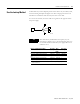
Results
power
supply
section 1 section 2
122m
(400 ft)
91m
(300 ft)
37m
(120 ft)
49m
(160 ft)
D1
91m
(300 ft)
122m
(400 ft)
D2 D3
D4
D5 D6
TT T TT
T
PT
1.10A
1.25A
0.50A
0.25A
0.25A
0.25A
TR
TR
TR = terminating resistor T = T-Port tap
PT = PowerTap tap D = device
41857