
Design Installation Guide Owner's manual

Publication DNET-UM072C-EN-P - July 2004
Determine Power Requirements 4-15
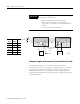
Adjusting the configuration
To make the system operational, you can:
• move the power supply in the direction of the overloaded section
• move higher current loads as close to the supply as possible
• move devices from the overloaded section to another section
• shorten the overall length of the cable system
• perform the full-calculation method for the segment described later in
this chapter for the non-operational section
• add a second power supply to the cable system (do this as a last resort)
as shown in the following three examples
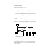
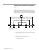
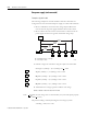
NEC/CECode current boost configuration
If the national or local codes limit the maximum rating of a power supply, use
the following configuration to replace a single, higher current power supply.
This configuration effectively doubles the available current. Essentially, each
segment is independent of the other and is a “one power supply
end-connected system”. Use Figure 4.5 on page 4-8 for each segment. Each
power supply can be rated up to 4A and still meet NEC/CECode Class 2
current restrictions.
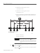
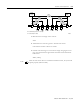
power
supply
PT
TR
TRT T T T
D1 D2 D3
15 m
(50 ft)
30 m
(100 ft)
122 m
(400 ft)
244 m
(800 ft)
1.0A 0.50A 0.50A
D4
0.25A
TR = terminating resistor T = T-Port tap
PT = Power Tap D = device
31514-M